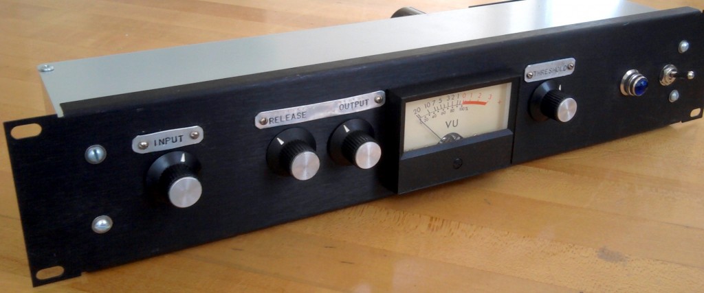
 In a previous post, we looked at the Altec 436 vari-mu tube compressor. I built one of these a few years ago, and it never really got used all that much because the output level is so hot. The 436 is a very primitive compressor design, and it sounds awesome- but it was also built primarily for service is installed sound systems: industrial paging use, etc. The stock 436 circuit adds a lot of level to your signal if you have the input level set high enough to actually cause significant compression. I built an external attenuator box using a 600-ohm Daven T-pad attenuator and a UTC transformer to re-balance the signal, but this was not really an ideal solution. The box was pretty big and heavy and I generally could not be bothered with taking it out and setting it up.
 The solution came to me when I was examining the circuit of the Gates sta-level. Here’s the schematic if you want to take a look. Now, this may look a lot different than the Altec 436 schematic, but the differences are not too significant – other than the fact that the gates has a regulated power supply, the circuits function in the same way; the main difference is the particular types of tubes that are used. Both are fully-balanced vari-mu compressors which are staged as (input transfo)-(attenuator pot)-(vari mu input amp)-(driver stage in Gates only)-(output amp)-(output signal rectified, timed, and sent to grid of input stage to regulate input stage amplification)- (output transfo).
The Sta-level, however, has an output level control, whereas the Altc 436 does not. So how do they implement this?
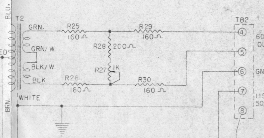 Pretty simply. 5 resistors and a normal linear taper pot give us an output loss that we can vary between 10 and 16db, while still maintaining a safe operating impedance. In all fairness: the BEST way to do this would be to use a balanced H-pad variable attenuator, which would give us the ability to vary the output from NO loss to, say 20db or so; but balanced H-attenuators are crazy expensive and very large physically; too large to fit inside an altec 436 chassis, certainly. Another option would be to use a variable T-pad after the output transformer, and then add an additional 600/600 transformer after the T-pad in order to re-balance the signal (there is a certain vintage vari-mu compressor that works this way, but i can’t seem to recall which; anyone?). This solution is also not ideal from a cost and size perspective, although it would certainly be less expensive than the balanced H attenuator.
Anyhow, the major downsides to the ‘Gates-solution’ are: 10db loss is inevitable; output impedance will vary slightly with use of control; variation range is limited to 6 db span. Well; i used my output modded 436 in a session yesterday, and for what its worth, here’s what I can tell you: the minimum 10db loss is welcome – it put the 436 into the same basic operating range as my 1176 and Distressor; the impedance mismatch (into a Lynx Aurora) did not cause any audible problems that i could detect when used on guitars and drum machines; and the 6db control range was fine as well – i was dialing in levels and getting sounds into Pro Tools with no fuss.
****
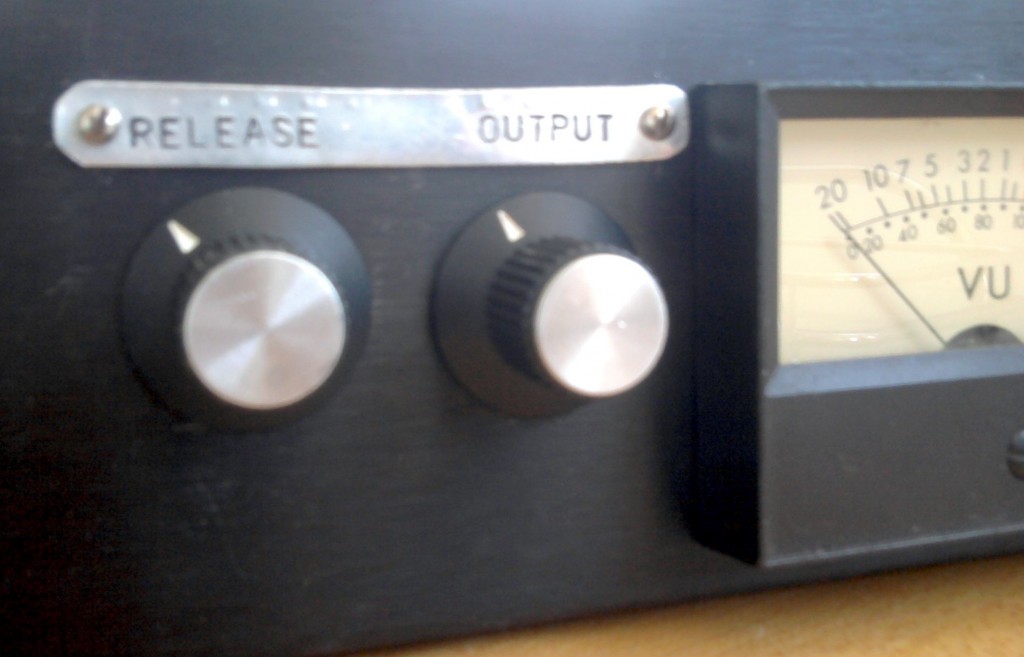
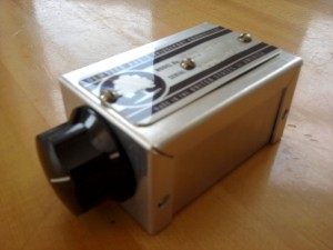
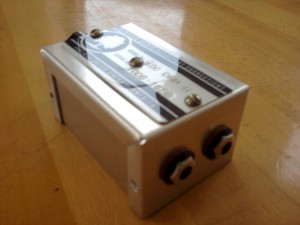
Before I drilled a fresh hole into the face of my 436 clone, I built the intended circuit into a tiny outboard box. When the design confirmed itself, I added the circuit into the 436 itself. But about this little test-circuit box: it’s lightweight enough that it can simply hang off the patchbay, supported by the patch cables themselves. Now every vintage mic preamp that I have can be given variable output control quickly and easily. This will allow me to dial in extra-gritty sounds using the preamp gain control (which is generally interstage rather than input or output), and then use this little device to get the level back down to an appropriate level to hit the convertor.
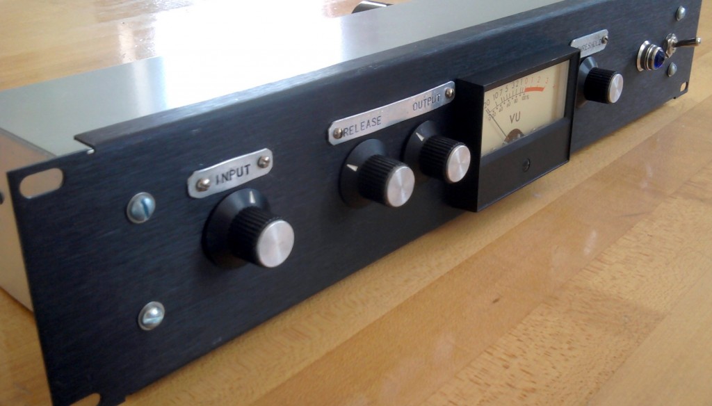 If you own a vintage Altec 436 or 438 and you find that you have to battle the high output level, I highly suggest that you give this modification a shot. It’s very easy to simply build it into an outboard project box at first in order to see how you like it before you drill a hole in yr Altec. And if you use any vintage tube gear in the studio: try making one of the little boxed-versions of the circuit. It will really open up some new creative and sonic possibilities for the gear you already have.
19 replies on “Altec 436 Compressor: Taming the output level: part 2”
Hello: I’m a novice with no electronic skills : I own an altec 436b and 436c: my basic question is what is the typical way to operate this compressor? and how do you know if its working? I am using a siemens V272 for preamp with an AKG D-12 for kick drum: sort of the Abbey road “Ringo” mike set up: kick and overhead: any advise would be appreciated: Dave Caputo
Hi Dave. typically: one wold plug the mic into the mic preamp, set the mic preamp gain relatively low (for a close-mic’d drum), then plug the preamp output into the 436, adjust the 436 controls to taste, and then apply a pad to the output of the 436 before going into your recording device. Typical useful pad values here would be approx 10db or 20 db. You can buy a fixed-value balanced 600 ohm H-pad from Markertek for about about $35.
Depending on the output of your mic and the intensity of the drum-hit, you might be able to skip the preamp altogether and simply put the mic into the compressor, but this is a long shot.
Great info! I’m considering buying a friend’s 436A– the older grey unit with the meter off to one side. It seems like that version does have an output attenuator… Do you know if that’s true? The unit in question is distorting with input and needs service so it’s hard to evaluate as-is. Do you think the 436A would be as valuable a tool as a “B” or “C” version? Just stumbled here btw, awesome site!
The 436A did not have an output atten stock. This does not necessarily mean that yrs does not have an output atten. The C is much more useful owing to the additional controls provided, but any decent tech should be able to convert an A or B to a C. I have done this for customers on multiple occasions. c.
I came across this thread whilst looking for a circuit for the 436B version. (Anyone with a circuit???) The preferred output (for me, at least) is a bridged H attenuator. I have fitted them to several Altecs now, all of the C variety, and if they are loaded with a 620 ohm resistor (which is close enough to 600 when loaded with 10k) they hold good for 20 dBs of attenuation, which is usually enough. they also preserve the balance of the output.
If anyone is interested I can put the details up on my website. You will need a combination of E24 and E96 resistors to get the 600 ohms constant impedance.. Attenuation is within 0.02dB at every 2 dB step.
I found your posting while looking for a solution to the problem of excessive output level on my Altec 436c, and would be delighted to see your design if you would be willing to share it. I was planning on building an attenuator and putting it through the fuse holder hole if possible.
Hi David. I did share it… it’s posted right there in the middle of the page… it’s the output atten from the Gates sta-level. just build that lil’ circuit, insert it in between the output trans secondary and the output jacks and yr in business. Good luck. c.
A variable attenuator that is!
Apologies for the imprecision in my post, I was requesting the variable H pad info from Clive who has a design that will fit in the Altec chassis, with a stepped attenuator.
I’m wondering if this design would be small enough to fit in the fuse holder hole in the faceplate of my otherwise stock 436C. Thank you!
Hi… Clive here. I’ll get it together and publish the values for the bridged H attenuator for this and other devices. You strap the output for 600 ohms and put this on it. It fits just inside the chassis to the right of the meter. It uses 3 wafers from the RS switch kit.
Look on my website in about 2 or 3 months (probably about August 2016) for the details.
TTFN
Hi Clive,
It’s been a couple of months… any update on the details for the bridged H attenuator for the Altec 436C? Couldn’t find it on your website.
Cheers,
Chris
Yes, + 1. I would also be interested in the variable H pad info from Clive. BTW, is that Clive Kavan of 3M U.K. technician fame? Thanks!
Yes… I certainly am! See previous comment for details of the pad…
That’s what I’m saying! I just got so excited when I saw the legendary Clive Kavan was possibly going to share his attenuator design I forgot my grammar and sentence structure.
I went ahead and tried the Gates Sta-level circuit, there seems to be bass boost of around +1.5dB at 40 Hz relative to 1kHz. Do we just live with this bass boost?
This happens with any pad combo, high impedance or low.
wow! that is so crazy. did u encounter this situation using an actual 436, with the original output trans? What impedance are you going into? 10k ohm? or 600 ohm?
I am gonna run a frequency sweep through the lil stand-alone version of the pad (https://www.preservationsound.com/wp-content/uploads/2011/05/Variable_h_pad_2.jpg) and see if I encounter the same thing.
TBC…
It is due to the action of the pad, but not the pad itself.
Putting in the pad allows more cranking of the input level control, since it’s now possible to due so without sending the device following the 436c into flames.
Interestingly it seems the harder the unit compresses, the bigger the bass boost gets. Up to about 3bD at 40hz, and more at lower frequencies. At least on my stock 436c. This is OK, I’m happy with the character of the compressor the way it is, I’m not looking to improve it. Well, maybe the DC on heater mod will get put in next. But it’s used for it’s character, I’m not interested in “fixing” the imperfections. Thanks for putting the info on the webpage, it helped get me motivated to do the mod. I used the values from the Sta-level schematic you link to, which are different than the ones right in your post. I used a 158 Ohm resistor in place of the 200 ohm and 1K pot, the 270’s on the input and 158’s on the output. This produced a loss of 18 dB and presented an impedance of approx. 600 ohms to the compressor output transformer. This is more or less unity gain with the input control at 4, and threshold at +10. With over +20 dBu input to the compressor the output is less than +10. I forget exactly the numbers, but it’s unlikely to cause a problem downstream, which was the complaint up to this point. Maybe this went too far, I’ll find out. Maybe one day I will get a variable pad made, but this will do for now.
Hi Chris
I have an original Altec 436c in which the output level is too high. The desk fader has to be pulled 20db lower with it patched in.
I don’t want to drill holes to mod it and saw that you had photo of a stand alone attenuator unit. Is the output simply plugged into it or is invasive surgery required? Do you sell or make these or do you know where I might get hold of one.
Many thanks in advance
Hi Keiron. just buy a 20db barrel pad. many places in the US sell them for $5. Good luck. CR