 Download a three-page article from the September 1948 issue of RADIO ELECTRONICS on the subject of ‘Three Straightforward Amplifiers.” Author is John Straede. Schematics ETC are all included in the download.
DOWNLOAD: Three1948Amps
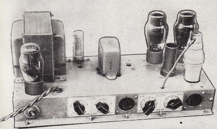
 Above, the most interesting of the bunch: a single-ended 6L6 amp which uses fixed bias for the output stage. I have never seen a fixed-bias SE power amp. Seems like this could yield some unique overdriven textures for guitar applications. Worth a look.
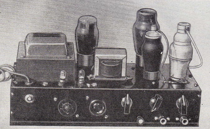
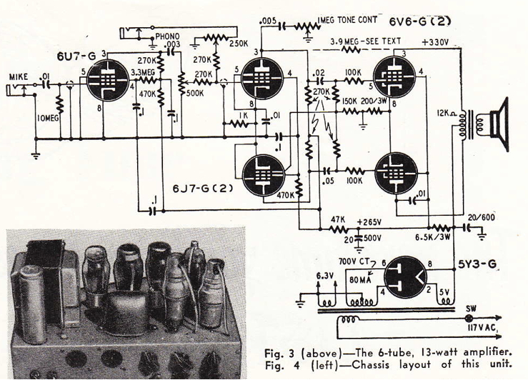
 Above, the 13-watt 6V6 PP unit. A couple of things to note: the input stage uses a 6U6 pentode. I have never come across a 6U6. Anyone use one of these? Also: the 6U6 stage uses ‘Grid Leak Bias,’ in which the cathode is at ground potential and yet no DC bias is used on the grid. I have never tried this type of bias. Anyone? Is it worth trying? What are the benefits/liabilities of grid-leak bias?
4 replies on “Three interesting Hi Fi Amps circa 1948”
Grid leak bias is well documented and was the standard early on in radio work. It’s undesirable for audio where there is a large dynamic range and is overly dependent on tube characteristics. Early Fenders used it and getting rid of it was one of Leo’s better moves.
Not having a radio background is a serious handicap many of the audio DIYers suffer from today. I consider building a radio or two a necessary dues paying activity.
These are not, in any modern sense, “high fidelity” amplifiers. They weren’t even by fifties standards. They are utility, public address amplifiers.
ya that’s certainly true… i should clarify… i tend to use the term ‘hi fi’ in a generic-descriptor sort-of-way to mean ‘consumer audio domestic audio equipment,’ kinda like most people use the term ‘Stereo,’ like, hey, Dave, turn up the stereo! Now, i would just USE the term ‘stereo’ but… it does’t really make sense for Mono equipment. so. Hi Fi. Not to be confused with actual High Degree Of Fidelity To The Original Recorded Sound.
the amplifier in the circuit shows a 6u7 g which i a variable mu rf pentode whereas the article calls it a 6u6 which is an output pentode 12 watts dissipation
a careful look at the circuit will show that the grid does NOT have a pin number because the valve has a GRID CAP ( consistant with rf/if amplifiers) the grid lead on the circuit shows that it is a shielded cable
a variable mu valve can be used for very low level input signals (here a mic makes sense) without gain variations/fluctuations in performance…
…the grid cap would have conveniently connected to the tp of an ”if” transformer with a very short lead…