 I picked up the above-depicted Pioneer SR-101 all-tube Stereo Reverb unit for a few dollars at the final flea of ’12. It worked after some minor repairs and I am happy to report that it’s actually a pretty fine lil box. I made a few modifications and added some hardware to adapt it to studio use. I’ll describe the whole fandango here in case any of y’all are thinking of going down the hardware-analog-reverb path. There are plenty of these things on eBay, often closing in the $50 – $200 range. Even if you have to spend a lil time or money on some repairs, it could still be a lot cheaper than the roughly comparable Orban 111B or the Sound Workshop 242, both of which we also have + love at Gold Coast Recorders.
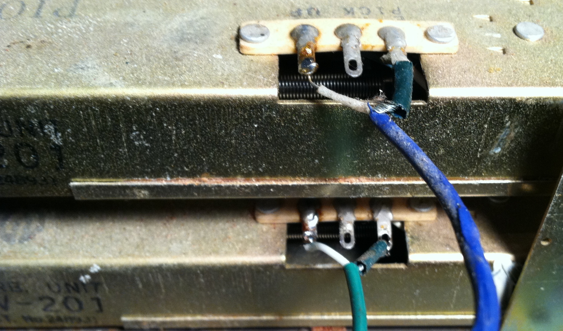 Above: the ‘pickup,’ AKA ‘output’ side of the twin tanks. Unlike the Fisher Space Expander (which I also just picked up… deets on that one soon…), the Pioneer is a true stereo machine. Each input feeds its own physical reverb tank. This is a big, big benefit over the mono-summing of the Fisher. My SR101 unit was passing direct signal, but not reverb, on one side; the culprit was actual just the output lead of the tank (above), which was over-heated during manufacture and had a signal-leak-to-ground on the coaxial cable. A quick snip-n-solder and we’ve got SOUND.
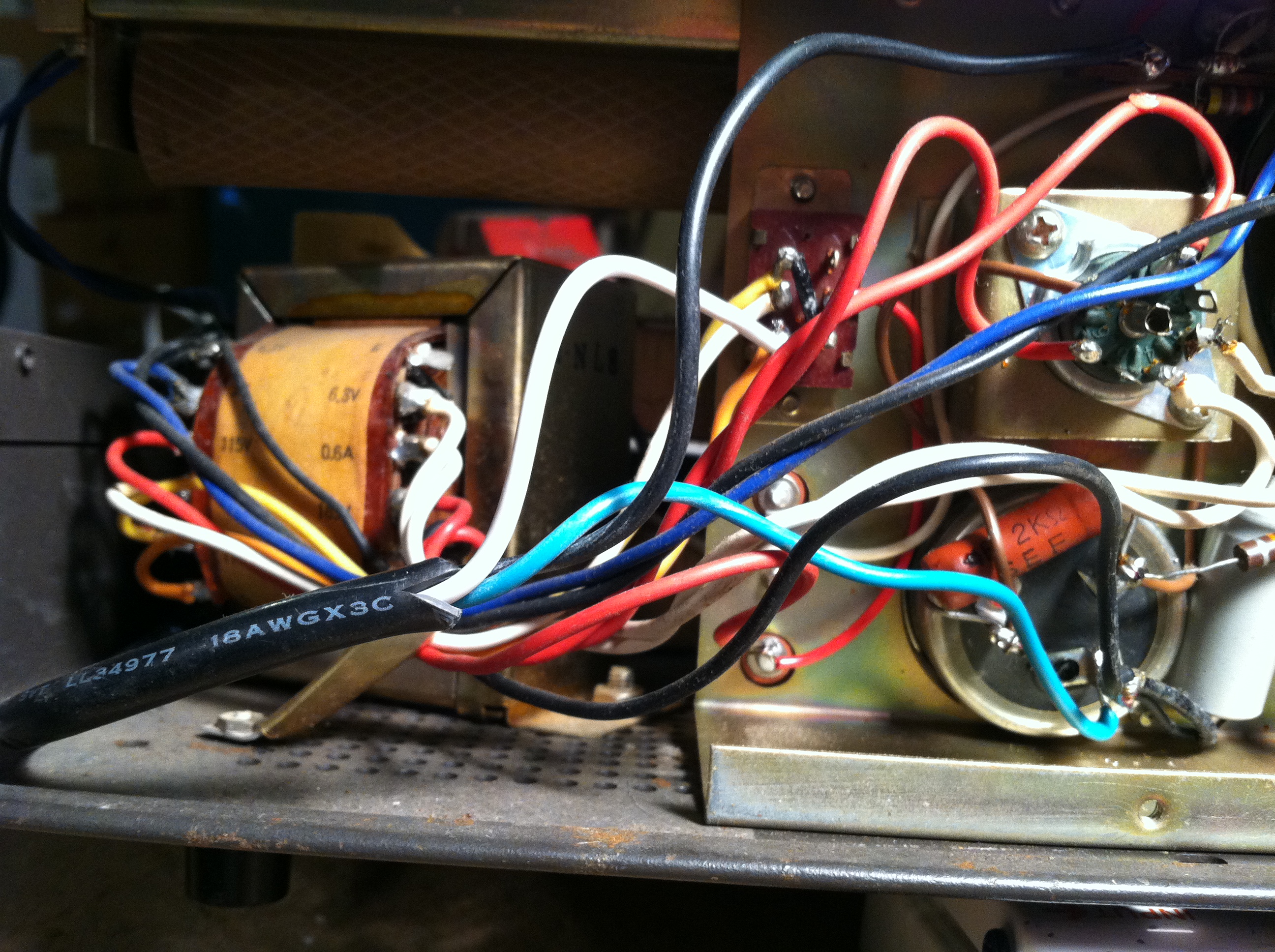 Because this is 60’s piece, the AC mains are not grounded. So I hacked up a nice long IEC cable and added that. Above: I connected the ground (green) wire to the common lug of the multi-cap cap. Seemed to be the most convenient option… The only other repair was of a more mechanical nature. The tanks are suspended from steel risers via small springs, with foam rubber pressed between the tanks+chassis. 45 years of tiiiiiiiiiiiime marching-on had turned much of the foam suspension into sticky goo; I replaced the rotted foam with some generic foam road-case-material.
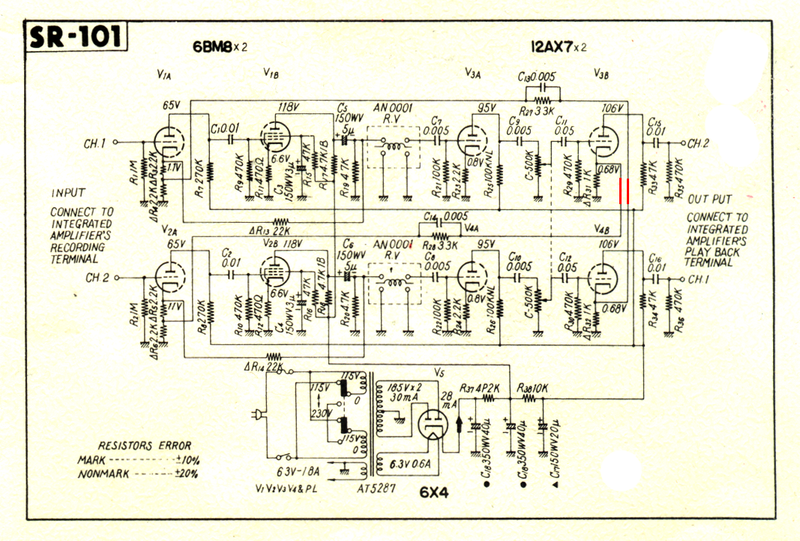 Above: the schematic of the SR-101, courtesy of this handy web forum. Notice the two red wires: the fellow who originally posted this schem was kind enough to highlight them. Here’s why. When I originally got the unit, it was a little tricky to troubleshoot; the left input came out of the left dry output, but the left channel reverb emerged from the right out. WTF? Turns out that this was a gimmick that Pioneer used in order to ‘widen’ the stereo effect. And it does work, but that would just be confusing as hell in the studio. So I re-reversed (versed?) the direct-signal wires and then reversed the leads going to the RCA output jacks.
 While I was at it, I drilled a hole in the front panel and added a DPDT on-on switch that cuts the direct signal fully out-of the signal path. So now the left channel input and its associated reverb both emerge from the left output, as one would expect, and vice-versa for the right channel. PLUS, now I can flick the switch up and get reverb-only in the outputs. Easy enough…
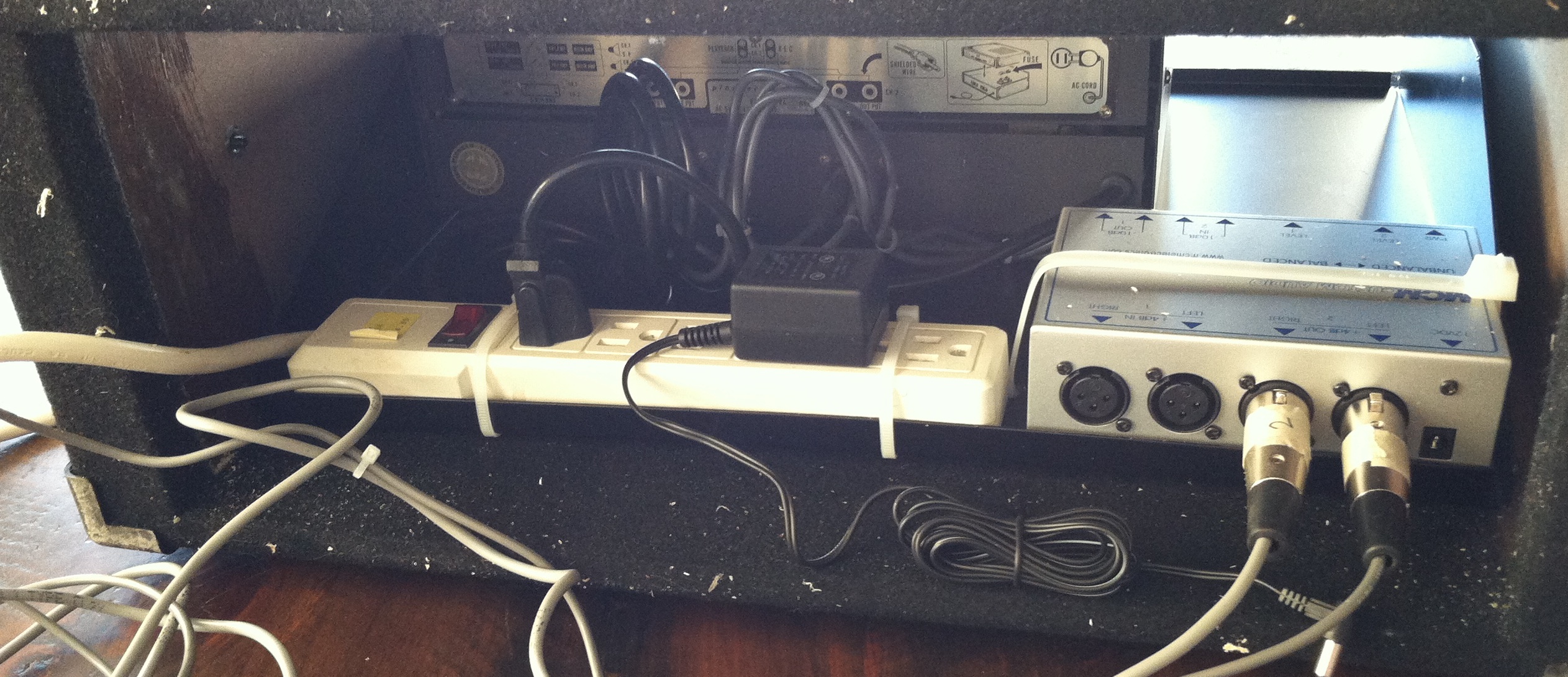 Above: the rear of the rack-case. That lil silver box on the right is a bi-directional stereo balancing amp designed to interface consumer audio gear with studio (or broadcast) audio systems. Basically, it takes a stereo balanced +4 input signal and drops it to -10 unbalanced output, and simultaneously takes a -10 stereo input signal and boosts it to a +4 balanced output. I own many of these sorta things, but the unit above is notable in that it is really, really, really fukkin cheap. These things are generally in the $70 – $200 price range, but my fav purveyor of dirt-cheap electronic crap MCM electronics has em now for $39. There are often sales too; I think I paid $35 for this one and $30 for the last one I bought. Both worked fine BTW. Anyway, I wouldn’t recommend that you mix a record thru the thing, but I can’t imagine it doing any harm to the signal coming from a 45-year-old box of tubes and springs and carbon-comp resistors.
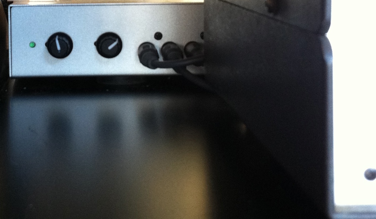 Above: the front of the balancing amp as seen from front of the rack-case. The knobs set the send and return levels to and from the SR-101. This is super-handy in terms of setting the right nominal level to ensure a good signal-to-noise ratio without creaming the tanks too hard (wow that sounds gross). Unlike the reverb tank in a fender guitar amp, for instance, the SR-101 hits the tanks with power amp tubes (around 2 watts, as opposed to maybe 100 milliwatts in a fender). So it is possible to get a pretty good signal level out of them without too much objectionable noise in the tank return circuit, provided that you hit the tank input hard enough. I might be repeating myself now, sorry, it’s late…
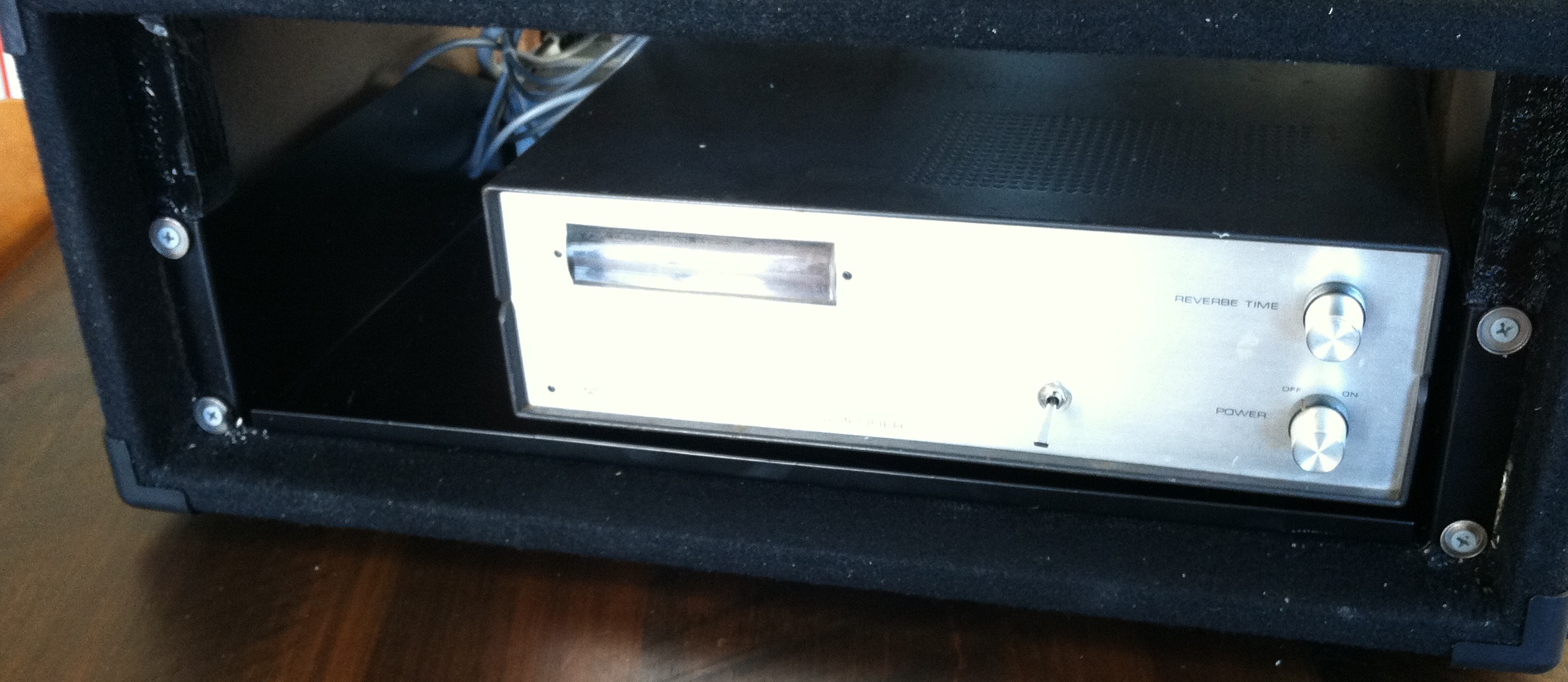
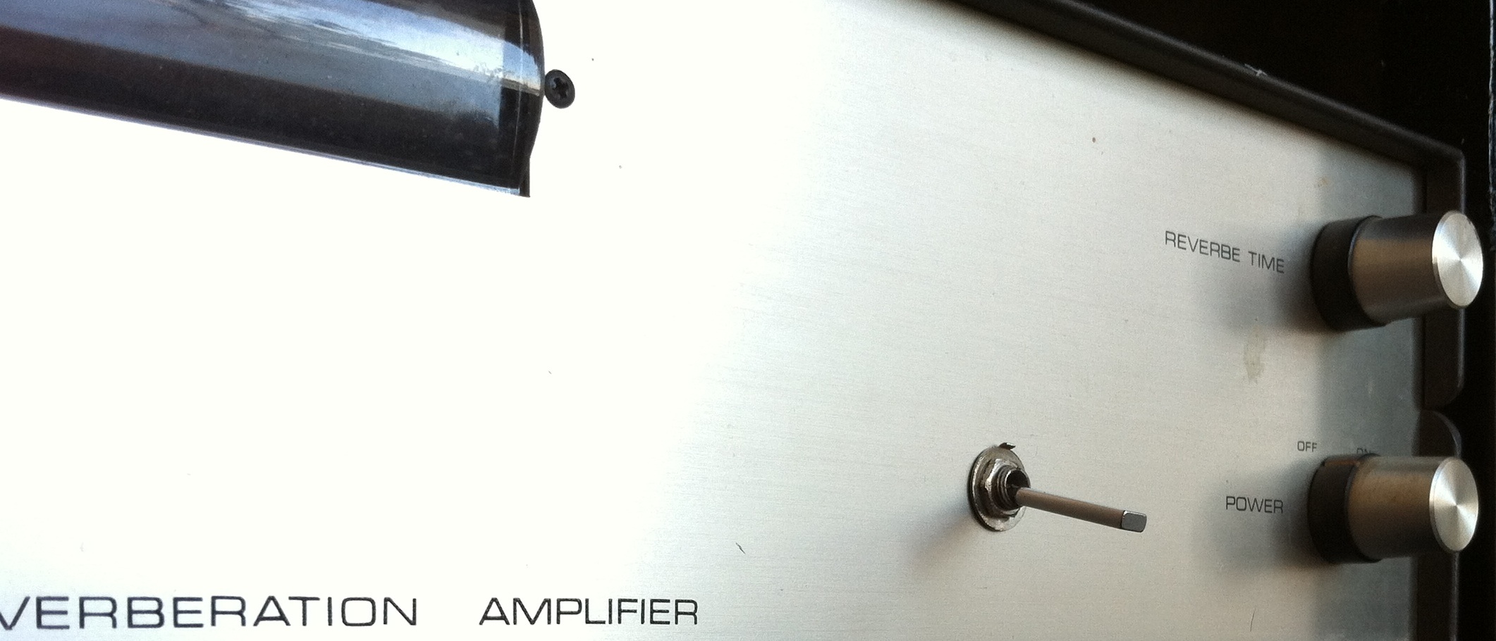
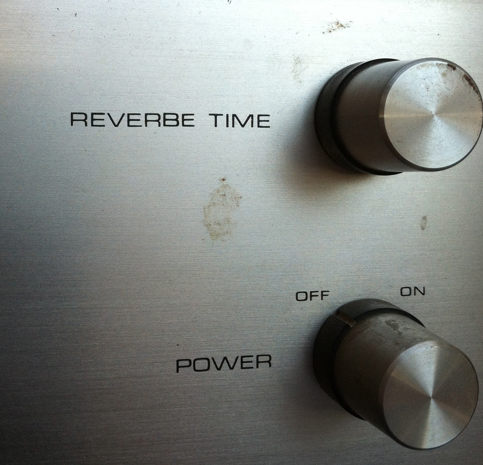 And above: the sole audio control on the unit, charmingly labeled ‘REVERBE TIME’ Yes Reverbe. Love it. As the schematic reveals, this is simply a passive gain control in the tank pickup amps. So yeah it’s a one-sound box. But it’s a glorious sound. This dusty gem just got put in GCR today, so once I get a chance to try it on a mix I’ll post the results.
27 replies on “Pioneer SR101 ‘Reverbe’ Unit”
Wow, I used to dismantle stuff like this for parts to fix guitar amps up with. That was when it was like pulling teeth to buy the “Correct” parts for Fenders. There were no Mojo, WeberVST, etc, etc back then. It had only been a couple of years since the aftermarket hot rod guitar parts industry even started making parts you could use to build or fix a guitar with except through authorized dealers at ruinous markups.
We’d put output transformers from Fisher, Scott, Pioneer or Sansui receivers in small guitar amps: power transformers you could get from Stancor or Thordarson, except they never had the bias tap so you had to cobble up a bias supply with a backward surplus filament transformer.
That ended pretty much when Fender was bought out from CBS and the new distributor was a lot easier to deal with, plus Mesa Boogie and others would sell these parts too. We have it really good now, by comparison, especially if you have a state business license and tax ID. It was fun to gut out all that old junk, except now it’s valuable and in demand.
Interesting to note that that schematic looks just like the ones in MJ to this day. Surely the old draftsman still isn’t working there? Or maybe he is.
the interior construction also has a somewhat MJ vibe… at least those cool recessed tube sockets, which seem pretty uniquely japanese.. Cheap as this thing prolly was at the time, ya kinda can’t fault Pioneer; it’s a 45 year old piece that needed no caps or resistors changed. that’s pretty good quality in my book….
“it’s a 45 year old piece that needed no caps or resistors changed.”
[…] Click here for some previous tube-reverb system action on PS dot com […]
[…] a a DIY’d mono tube unit based on the classic Fender tube 3-knob, and we recently added a mod’d Pioneer RS-101 stereo tube reverb to the lineup. In addition, I use a built-out Fisher Space Expander in my lil home studio. But […]
Would love to modify mine the way you did (especially for the dry out part) would you post where you did the mod on the schematics? thanks best K
Hi Chris i just found this post and i have just bought a pioneer sr 101 and plan on doing som of your mods im not sure about the DPDT do you think you could help me with the install thanks Ozzy
Hi Dan, any shop that services guitar amplifiers should be able to do this work for you. good luck! c.
Hey Chris,
A client sent me one of these for repair and it had exactly the same faults as yours did,
right down to the shorted tank wires. I repaired it, reversed the reverb feeds and added the direct out bypass switch. Everything works perfectly, thanks for your post,
it saved me a lot of time in troubleshooting.
that is great to hear charlie! glad to have been of help! c.
Charlie, I just got one with the exact same issue as listed here! How much does it cost to fix and apply the mods listed here?
Hi,
Would it be possible to modify a unit like this to work for recording guitar direct?
Hi Ian. sure,,,, anything is possible, but i don’t think it’s the best use of this device. you could certainly sacrifice one channel and re-route its two 12AX7 stages to use a preamp to drive the line-level input of the remaining channel. Come to think of it, it would only require moving a few wires and adding a couple of parts. But why bother? You could instead just buy one of those little ART tube preamps on eBay for $30 and use that to drive both channels with a guitar signal – and then you would get psuedo-stereo verb.
Hi Chris,
Thanks for posting this! I’m currently working on an SR-101 myself, attempting to sort out the outputs. Prior to modifying yours, would you say that the reverb was much more apparent on one side than the other? I’m currently confused as to whether one of my tanks is going bad or if I’m just hearing this “widening.” I get faint reverb and a strong, clean signal from the left (I believe) channel and a somewhat strong, very reverberated signal from the other. I’ve swapped each channels tubes out and touched up a few solder joints, neither of which helped.
I would love to know your thoughts. Thanks!
I should have said “a somewhat present clean, mixed with a very reverberated signal from the other.”
Basically, when I return it to my console, it sounds like the reverb is panned right.
Hey man. One would need to do some basic trouble shooting. Either the thing is hooked up wrong or you have a fault in one of the channels. Start by using a signal-generator (rather than music) as a source signal. Beyond that, I cannot advise on the repair of high-voltage equipment as it is potentially hazardous. There are plenty of cheap old military training manuals that can teach you to troubleshoot tube gear. Good luck. c.
Oh, sorry, should clarify. I’m not really looking for specific advice as to how (or if to repair it), but more if that was the similar characteristic of sound that you experienced, prior to modification. Despite my obvious lack of experience, I have modded and rebuilt a few tube pieces before without killing myself. Mainly here, I’m trying to get some sense of what this thing is “supposed to” sound like in it’s stock form.
I’m reading that a lot of other people have had similar experiences (the same actually) as I have with this unit, leading me to believe that: A.) This is a very common issue or B.) This unit is supposed to sound this way.
Given the strange manner in which this unit mixes audio and the fact that there are only four connections on the chassis to work with, I can only assume that this is the way that it’s supposed to sound.
Would love your feedback on that though. Thanks for the response!
Both channels should sound similar. If not, something is wrong, either in your hookup/playback apparatus or the internals of the unit. good luck – c.
Do you have an photos of where you moved the wiring around to get left to be left and right to be right? Finally getting around to modding mine now, and any steers would be appreciated. Thanks Barry
Very instructive repport, and very interesting website !
Mine is now repaired, with the help of the schematics.
A faulty resistor on the input…
It’s sounds very powerfull, wide, and not much noisy !
But, can you please show us the points for the DPDT ?!
Bruno from France !
Sorry for such a late response to an old thread. But, better late than never (I guess)… The two wires reversed in the schematic appear to be the CH 1 and CH 2 FEEDBACK loop wires. Seems, at first glance anyway, that the unit utilizes the feedback circuits of channels 1 and 2 to mix the reverb signal in OPPOSING polarity to the originals. Cheers.
i got one of these..i love it. one channel sounds way better than the other channel but it’s a great sound.
i haven’t rewired the stereo of mine because i actually like to saturate the uneffected side
j
0=0
Hi all,
For what it’s worth, I spent some time debugging my recently purchased SR-101 and adding the dry-cut mod. In the end, even with fresh tubes, I couldn’t get rid of a pretty aggressive buzz (15 to 20 dB SNR) until I realized that the heaters weren’t ground referenced! Balancing them by tying both sides to ground through 1/2W 100 ohm resistors essentially eliminated the buzz for me. I did this for both the audio tube heaters and the 6X4 heaters just for good measure.
I learned about this “humdinger” configuration from Merlin Blencowe’s books. Essentially, the rectifier tubes in the high voltage circuit creates pulses in the transformer which couple to the heater circuit, which then couples to the audio path. Not sure how they overlooked this in the original design! This reverb sounds amazing now 🙂 if anyone in Brooklyn needs help on their sr101 (or anything else) feel free to send me an email or follow @yumyumaudio on Instagram.
All the best,
Ben
I bought my SR 101 new. Haven’t used it in many years. Will it work with the newer multi channel units and what would be the best hook up procedure.
I’m confused as to why a DPDT switch and not just a DPST?
Is it not just a case of breaking the circuit of the 2 red highlighted cables?
Many thanks in advance.
Hi, my SR-101 sounds fine powered up, but a loud hum increases as the “Reverbe” level is increased. Also, it sounds like most of the reverb is on the right side. I have zero knowledge of electronics, so took it to be serviced and was told that the sound was fine and there was no hum. I thought, maybe it’s my old phono cables, so bought brand new ones, but still have exact same issues.
I don’t know what this guy was hearing when he tested it. Could be something about my particular setup at home that’s making the hum? But if the hum only relates to the reverb control, doesn’t that indicate an internal problem rather than external, cables, other connected units, etc?
I see other comments that sound like they could describe the same issues I’m having, but the fact that a professional said it was all fine has made me confused… I’ve heard recordings of the unit on YouTube, and there doesn’t seem to be a noticeable hum, so I don’t think mine is normal.
Could anyone help point me in the right direction? Thanks 🙂
I found one of the “reverbe” 500K pots was bad. It caused noise to increase in one channel as reverb was increased.