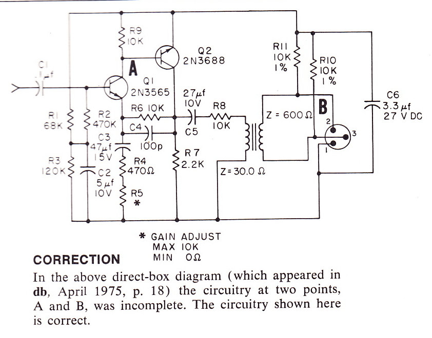
 From DB magazine, June 1975: a direct-box that was custom-designed for Leon Russell’s studio. I am a huge LR fan and once I dig up a 30:600 transformer I am gonna throw one together. Question for you solid-state guys: 2N3688 is no longer available; is there a ‘preferred’ substitute? And: 2N3565 seems crazy expensive! $11! is there a cheaper sub?
Categories
10 replies on “Leon Russell’s Direct Box circa 1975”
I don’t know if I’d bother with it, but when you throw this one together: C6 (3.3µV, 27V) filters the phantom power. As it’s a 27V part, this DI box has most likely been designed for a voltage of 24V or even 12V. Almost all currently sold gear uses 48V, so please use a sufficiently rated part. C2 and C3 run at 2/3 of the rated voltage, just use the exact same part as C6 to make it easy.
Also pay attention of the breakdown voltage of the transistors you choose. When you turn on the machine, Q1 will see the complete phantom power, and it seems that ‘3565 is only rated 25V, It would be a shame to spend 10 quid on a transistor just to see device after device blowing up…
Super helpful. thank you Christian! c.
What are the parameters of these devices? With that information a recommendation could be made.
i have no idea…. i never mess with transistors. i guess i was hoping that these were ‘common’ types such that someone might know a sub offhand… i guess that, unlike tubes, which exist in relatively small types/varieties, the variety of transistors is so wide that it’s less likely that someone might recognize the part number.
There are probably as many tubes out there as there are transistors, it’s just that audio people typically have no idea about what else tubes were used for.
You are going to have to narrow the search down to likely candidates in terms of sex, dissipation, gain, voltage and frequency range. We know we are looking for NPN small signal transistors in the 25-50 volt range working at audio, so that narrows it down. Likely you will have to try several plausible candidates in circuit to see what works best.
Determining who made those parts and obtaining a transistor manual for them would be helpful. An ECG semiconductor replacement guide might also be a place to look. I used to have a lot of those things but when I moved they had to be discarded. An ECG manual might be online.
Ever get this thing working? Sounds like a good project.
haha no way… not yet… eventually; maybe the next snow-day.
Unless someone was playing a joke, or the schematic is really for Leons fuzz box, there is a glaring error in the schematic, as drawn and labeled.
Yes, 2N3688 is an NPN transistor.
But, a PNP transistor is required in that position for that circuit to operate.
The 30 Ohms to 600 Ohms is also clearly a misprint. They probably meant 30k Ohms to 600 Ohms, which is a 7:1 Voltage ratio.
The circuit appears to be designed to operate on +15Vdc when powered from a standard +48Vdc phantom supply (through 6.8k resistors).
Since the circuit, as specified, will have 50dB of gain, it will be able to handle about 15mV r.m.s. of input signal (which is about what you get from a single coil (Strat type) pickup) before clipping, which will happen at about 5 V r.m.s. With a 7:1 Voltage loss in the transformer, the output would be about .7 V r.m.s., which is about right for a “hot” microphone signal.
To come close to duplication of the performance of the original, I would use 2N4401 for the Q1 and 2N4403 for Q2.
To improve on it, I would use an MPS-A63 Darlington NPN for Q1 and change R2 to 1 Meg Ohms. This change will allow the circuit to present a much higher input impedance to the source. As altered, it should load a pickup about the same as a Fender tube type amplifier.
TG
Aural Technology
Addendum to previous comment:
I just noticed the 10k resistor in series between the amplifier output and the transformer.
The 10K resistor does isolate the amplifier form the transformer enough that the circuit could operate reasonably well, even into 30 Ohms.
However, assuming the transformer truly did have a 30 Ohms primary, this creates a 5odB pad, which is followed by a step up through the transformer of 13dB, for a net gain from the input of 13dB. Pretty strange. I’ll stick with my assertion that the transformer primary should be 30k Ohms.
Great info tom Thanks so much. C.