 So I was flipping through Recording The Beatles recently and I was reminded that I had yet to make one of those famous EMI console preamps. As luck would have it, we were hit with a pretty major blizzard and I had a few days with nothing much to do. The preamp turned out great, I love the fast (fast for a tube/transformer circuit, that it…), assertive sound of it, and I will definitely be making more of these things. I’ve been using it primarily for tambourine (with a vintage Senn 409), acoustic slide guitar (with an Altec 660B), mandolin (with my Audio-Technica 813) and acoustic rhythm guitar and shakers (EV RE15).
Here are some of the resources that I used to build the device. I apologize to whoever originally posted these documents for my lack of attribution; I DL’d them so so long ago that I can’t recall where they came from.
DOWNLOAD: EMI-REDD47
Another Download: REDD47AmpSchem
And these two images: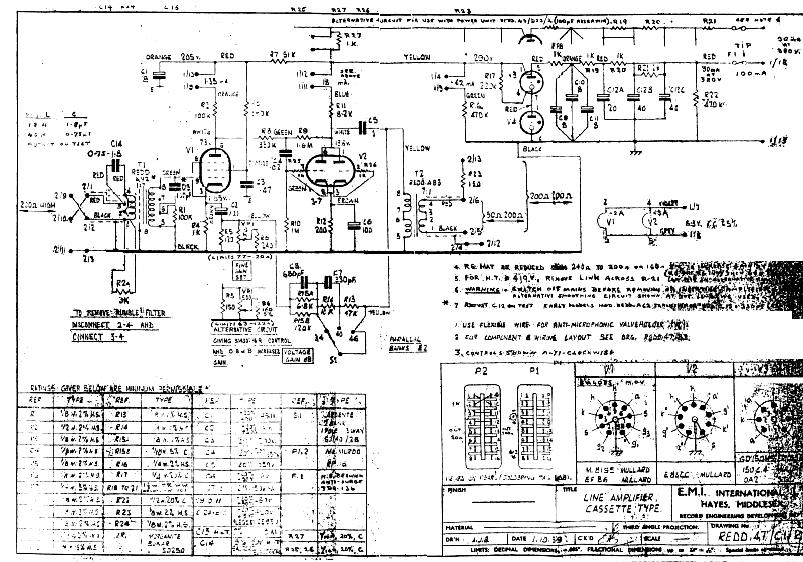
There is a real lack of consistency among these documents, and no I am not going to offer a ‘corrected’ schematic; that being said, if you actually have the where-with-all to fabricate one of these things from scratch I think you will do just fine with the same materials that I started with. And if you don’t want to do it from scratch: no problem! Just visit these dudes. (n.b.: I have never used a drip electronics product personally, so I can’t vouch for them; that being said, they are extremely popular and seem to know what they are doing).
A few build notes
I used my usual Jensen input transformer (click to DL info) and Edcor output transformer. The thing sounds great overall, so I recommend these, at least for a first-build of this circuit. Why spend more?
Very important: this circuit uses a lot of negative feedback. There are also a lot of capacitors in the feedback path. Each capacitor contributes some hi-pass filtering, which should be below audio range, BUT… if the capacitor values don’t all ‘play -nice,’ you could end up with so much phase-shift in the sub-audio region that there is 180-degree phase shift in the sub-audio region and you will have a device that ‘motorboats,’ I.E., your ‘negative feedback loop’ is a POSITIVE feedback loop aka a fkkn oscillator. I had this problem initially. The device worked fine, seemed to sound good, but at the lowest gain setting (aka the setting with the MOST negative feeback, get it????) I was seeing some 10hz signal pretty prominently in the audio files. I guessed that this was due to the fact that I used a 47uf cap by the cathode of the input tube, rather that 100uf that is specified. I made the correction and viola problem solved. HERE’S THE SHORT VERSION: with this much feedback, component values are critical. BTW, who knew that Apogee A/D convertors work so well at 10hz???
The Redd 46 has a three position gain-switch, and also a ‘gain trim’ control that does very very little. Think of it as a ‘channel matching control’ rather than a level control.
Because of the lack of gain control, and the fairly high minimum gain setting, the Redd 46 really needs pads to be used in the studio. Since I did not leave enough panel room to add i/o pads, I have been using it with some external 10 and 20 db ‘XLR barrel’ pads. Depending on the amount of drive and crunch that I want in the signal, I have been adding the pad either before or after the preamp (or both!) before the signal hits the convertor. Therefore, the next time I build one of these, I am going to include two two 3-way (0-10-20) switched pads in the device, one before the input trans and the other after the output trans. I highly reco that you do the same. I generally use a pad design similar to this one suggested by JLM audio; never had a problem with it.
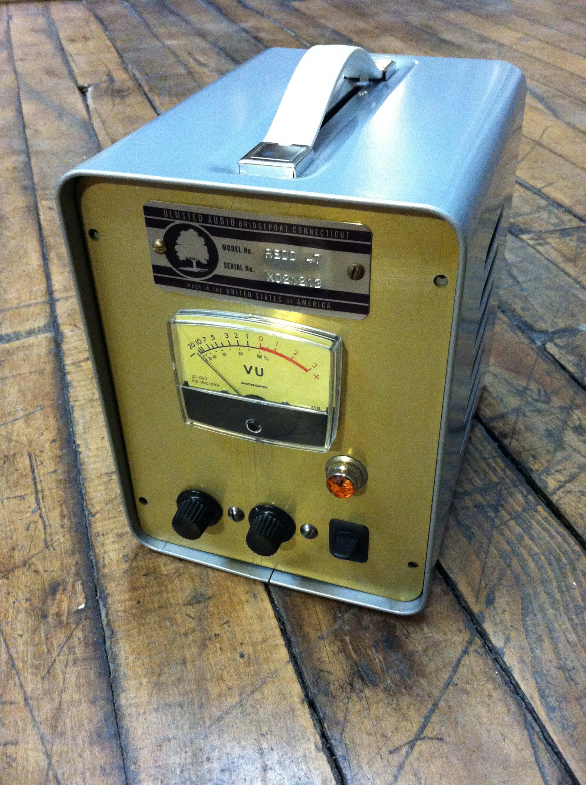
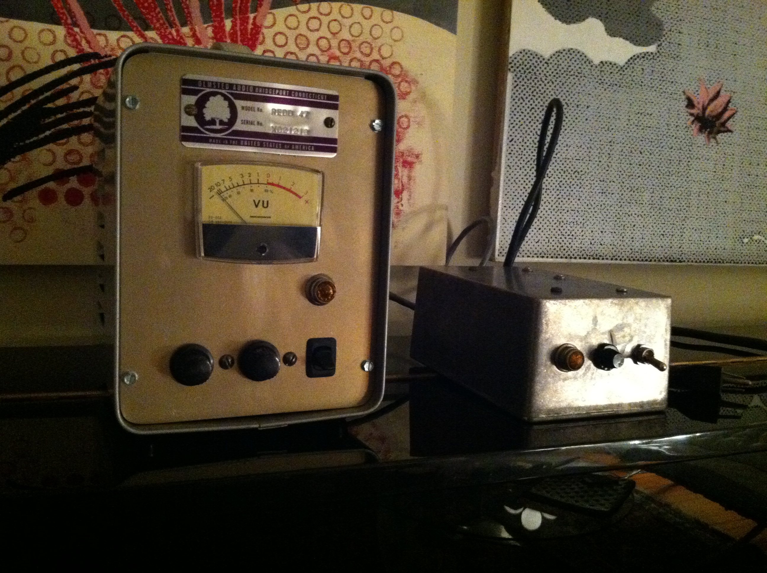 Above: another shot of my REDD 47; the box on the right is the power supply; basic voltage-doubler (ala the Altec 1566) with tons of filtering and a choke for the B+ and DC filament supply. Connection is by a 4-pin amphenol.
I have gotten a lot of questions regarding the enclosure used for the audio chassis: it’s a BUDD enclosure of some type, I can’t recall the exact product name; it was dead-stock from a local distro, last one they had, and I am guessing that it was manufactured in the 70s. No idea where to get more of them. If you know, please drop us a line…
19 replies on “EMI Redd 47 Mic Preamp build”
I see homebrew ham stuff in enclosures like this at all the hamfests. It’s fairly easy to just gut them and make a new front panel.
Hey There – superb site and blog.
I am just finishing up a 2-channel REDD47 point to point for my little project studio.
Love your REdd47 page and the info there – especially useful stuff on the pad switches. I am going to incorporate an output pad on my build for each channel. I have -20dB pad switch on the input ( a la Jensen standard mic input wiring )
Your build looks great – and I bet sounds excellent
here’s a link to my build – happy to share info and experiences on the REDD once I have finished it and starting using in the studio.
http://i55.photobucket.com/albums/g159/pedrocortez/69A6B2DE-8EEE-435D-B17E-9AC845458E95-680-000000C6C6437CE7_zpsd94c8241.jpg
All the best ,
Pete
Great stuff pete. thanks for sharing. and YES my redd47 circuit sounds GRT, i use it everyday, v v happy with it! Y’all should def check out petes’s build, great looking fabrication… send us more stuff Pete!
Hi Pete,
needless to say you’re work is perfection here. I wonder if you’re considering to make this project market-able.
Do you think “someone” can ask for a quote to buy one? BUILT! 🙂
This would be an awesome piece of gear for both project or pro-studios. Thanks. Alex
Do these builds have tone and character of like the Chandler Limited TG 2 or his version of the Reds 47? What are the be best resources for this type of build for Diy? I’ve looked at Seventh Circle Audio N72. I would love to use a unit like this on vocals and acoustic than run to audio interface than daw. After watching so many mic pre type, i.e. op amps, tube outboard, emulation mic pres, it seems these give the most in your face vocal signal and that would cut through a mix with analog smoothness and rich tone for classic rock like Rolling Stones,Beatle and Queen to name a few. Thank you for any info and should I look into Drip electronics? Another tone searching nut, Zach.
Thanks Chris,
I took your advice and am fitting balanced stepped attenuators on the output – do I need to worry about impedance matching here ? ~Some of the output attenuator circuits I have seen look very complicated in comparison – I like the simplicity of the 3-way attenuator. ( JLM style )
I have a 20dB input pad so the combination of the two should be all i need i hope !
All the best
Pete
Update : I finished my dual channel REDD47 and it really is a very good preamp. I recommend this circuit.
I fitted the JLM style attenuator on the output as you suggested and its a great addition.
I used Mullards in the signal path , and Sowter replica Redd TX’s on both input and output and there’s lots of bass response which is great. Early days yet ( not much tracking with it so far..) but the sound both mic’d and DI’d is superb.
Highly recommended pre to build.
Cheers
Pete
Can you please give some insight on the wiring of the VU meter — thank you, would love to see pics of everything mounted on the inside. Great build + enclosure;)
-Jeffrey
Sorry no more pics. It’s been installed at the studio and i’m not gonna take it apart at this point. RE: VU meters – the implementation of a VU meter depends on whether or not it’s a ‘rectifier’ type meter. Also you really should use a buffer amp to drive the VU meter otherwise you will get a little bit of rectifier bridge distortion on the output. JLM audio sells these for pretty cheap as kits. c.
thanks! Im designing the layout of my REDD47 right now, got all the parts salvaged, still need to find transformers, but not too stressed out about that since I can always save up for the Sowter copies. ill stay posted & if i have any questions i will be sure to hit you up :”)
thank you!!
-thee
Dear Chris,
Great work, love the chassis you chose to mount everything in. Man that sure is a wrecked schematic you were working from — great work pulling it off. How in the world did you ever read the Voltage limits on the Caps! If you have time &/or can remember the cap limits off the top of your head I’d surely appreciate your help figuring them out.
Best,
how much?
Chris …
what rectifier did you use in the project? or do you use diodes for PSU ?
Hi Andres. I can’t recall building this thing, as it was so long ago, but based on the fact that the supply is an unventilated box, i would assume it was diodes. Likely basic IN4007 diodes, either a pair or a quad (depending on whether the PT H/V secondary is center-tapped or not).
I believe the 82k resistor should be 8.2k . . . unless I just can’t see the decimal.
Hi Tyler. What makes you think that? I built this thing so long ago that i certainly can’t recall, but it did work GREAT…. 82K is a MUCH more likely value for a plate-load resistor than 8.2K, given the biasing configuration of the tube ETC. I am not saying you are wrong, I am just saying that plate load resistors in R/C coupled amplifiers are generally 75K to 330K. Please share your insights tho, I am no expert. CR
Just FYI, the anode resistance of the E88CC is guaranteed to be 8.2k not 82K. It is advisable to use a 5Watt type.
Hi Chris!
Thanks for creating this page!
Are you suggesting that the ‘Gain Trim’ circuit is unnecessary? Would you omit on future builds or simply that it’s not intended to be used as a gain control, but useful if using multiple preamp channels in stereo configurations or ?
Lastly, when you say you would build future builds using two 2P3T switches before and after the i/o transformers, do mean physically & mechanically directly before and after the i/o transformers?
Cheers
Nice!
The virtual 600 ohm impedance via serial R solution on the secondary siden of the output transformer made me a bit surprised though. It should be wound to 600 Ohms with a tap at 200 Ohms. But then you have to wind the transformer by hand.