Categories
Custom Fabrication

Bespoke Mic Preamp based on Akai/Roberts circuit

AC_Custom_front
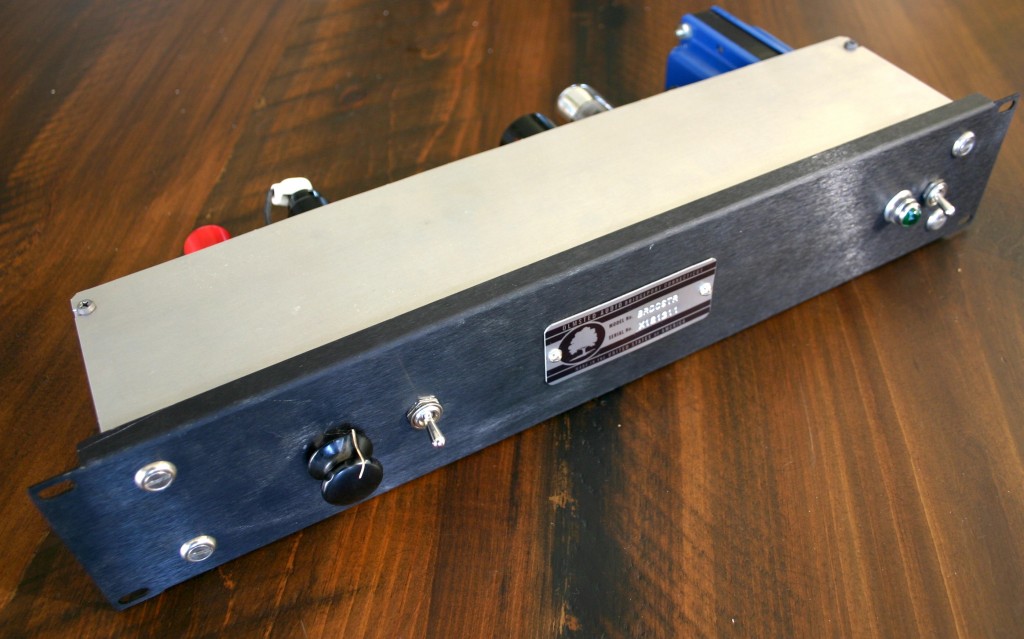
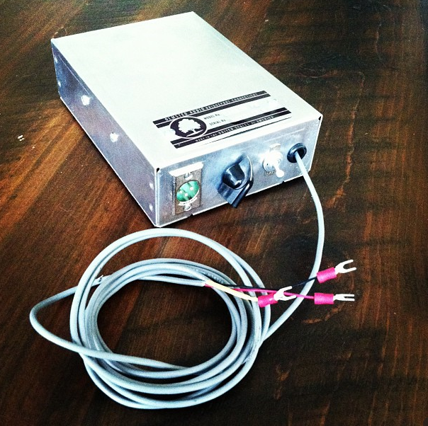
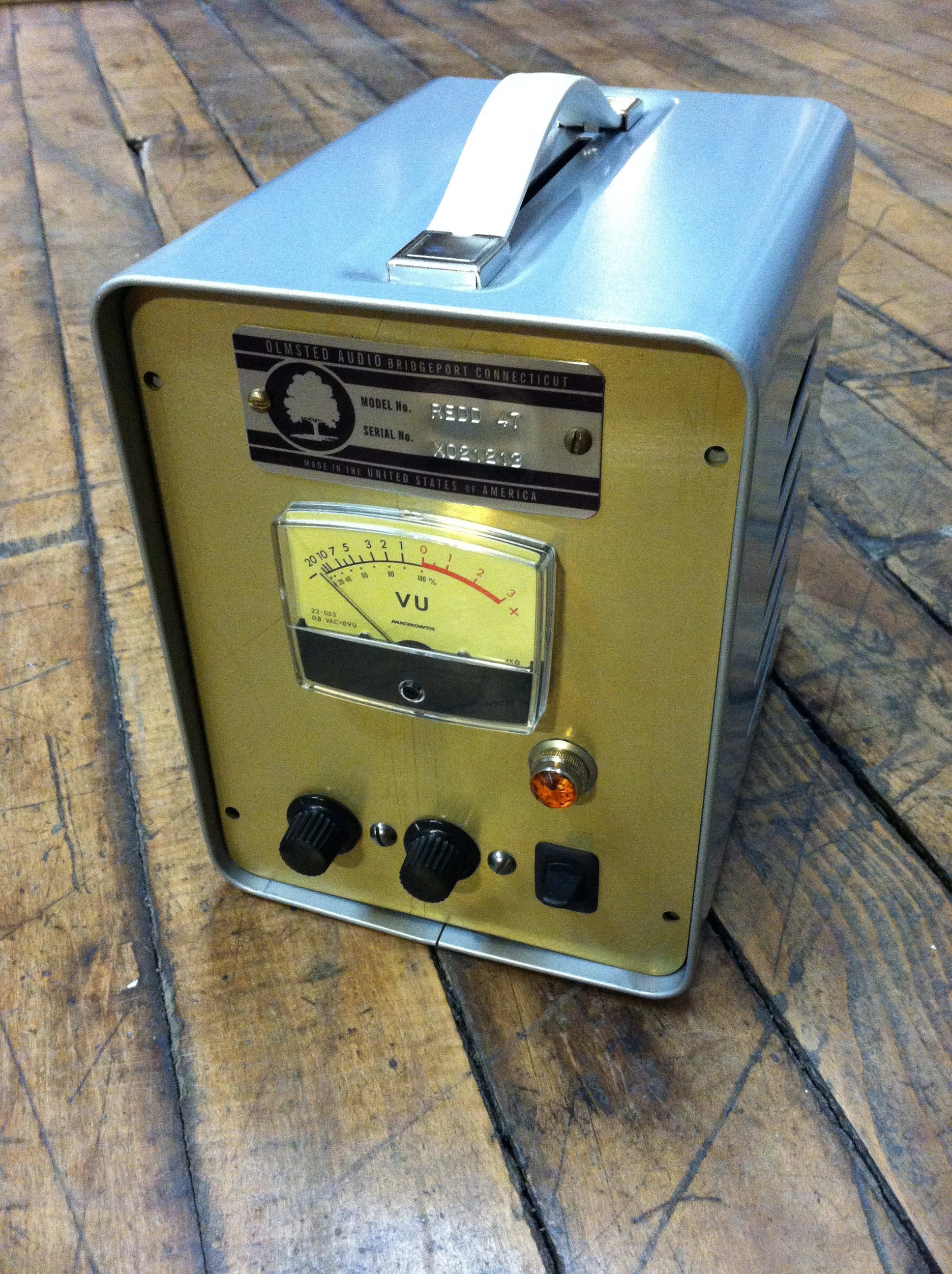
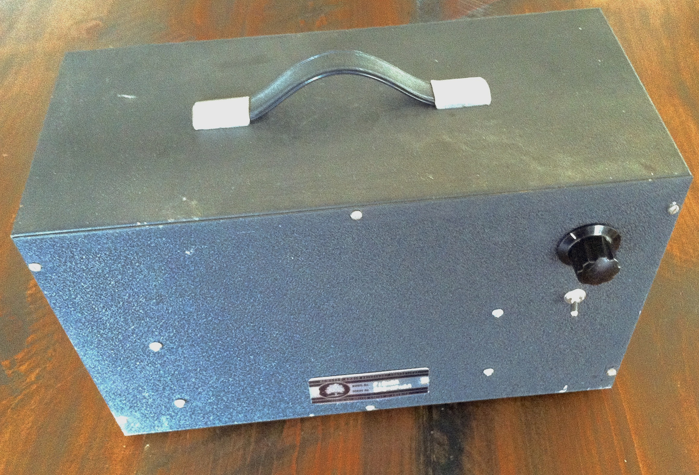
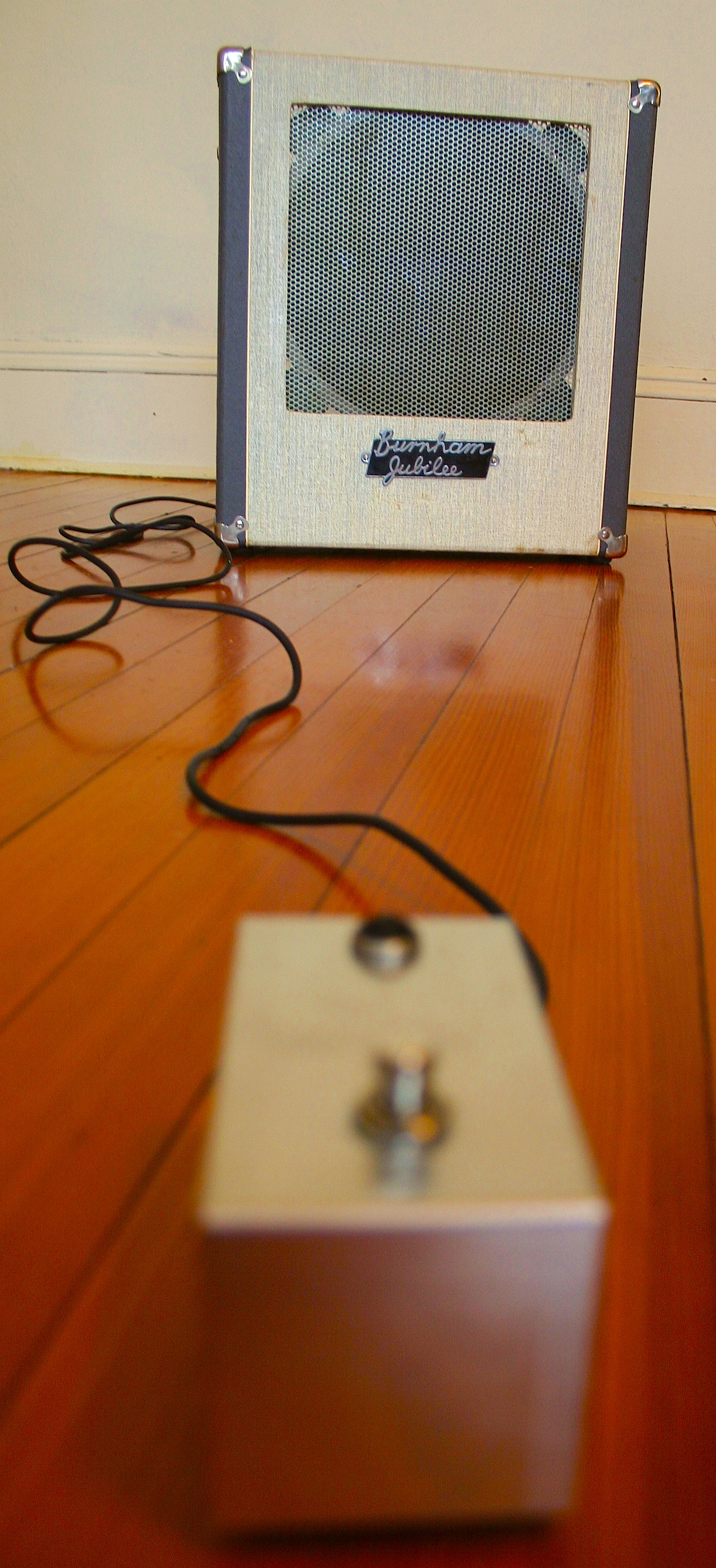
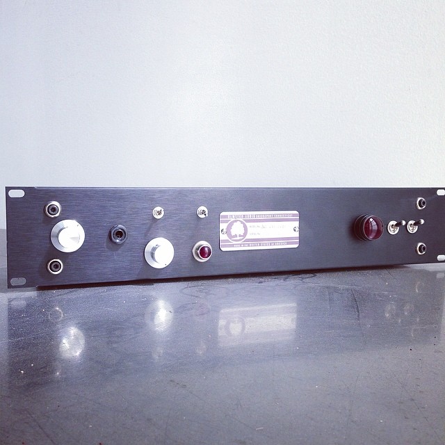
(Above: the prototypeakai_m-9_front
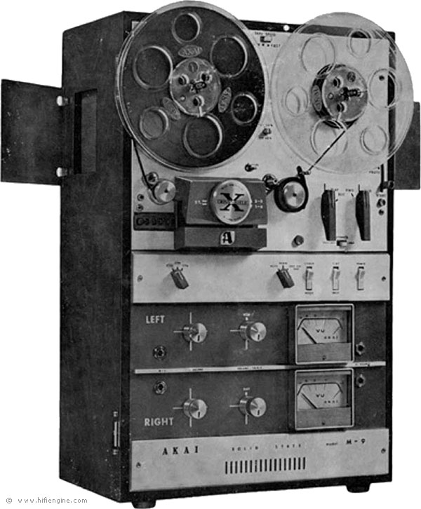
) Apparently there is a popular internet ‘meme’ based around the modification of these units (the same machine was marketed under both the Akai and Roberts brand names)Here’s an example of one of these DIY sites.  Handy types are encouraged to turn these stereo tape decks into four independent microphone preamps, and step-by-step instructions are available.   After a look over the instructions and forum info, it was clear that these mods would present some challenges for use in a pro studio – especially as far as impedance and output level are concerned.  My thought was: leave the Akai alone!  And spend the time instead on a fresh build that utilized the most significant/interesting parts of this project, add a ton of useful add’l features, and pushes full +22 output level at 600 ohms.

Akai M7 Right Schematic _MOD_2_Preamps_In_One
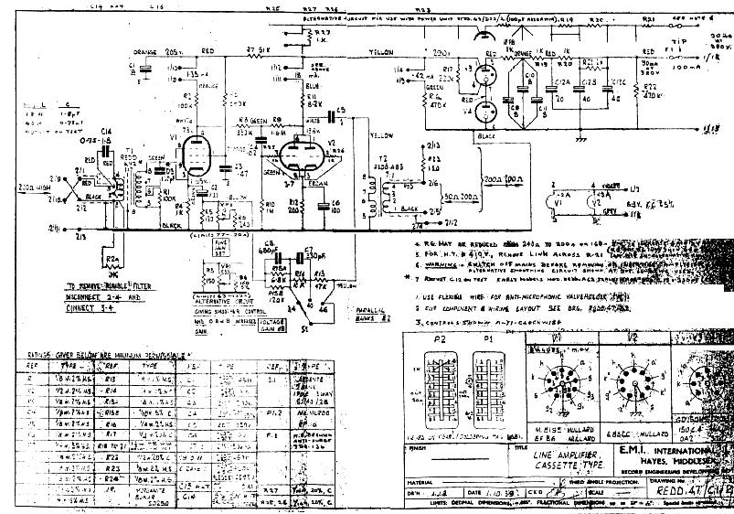
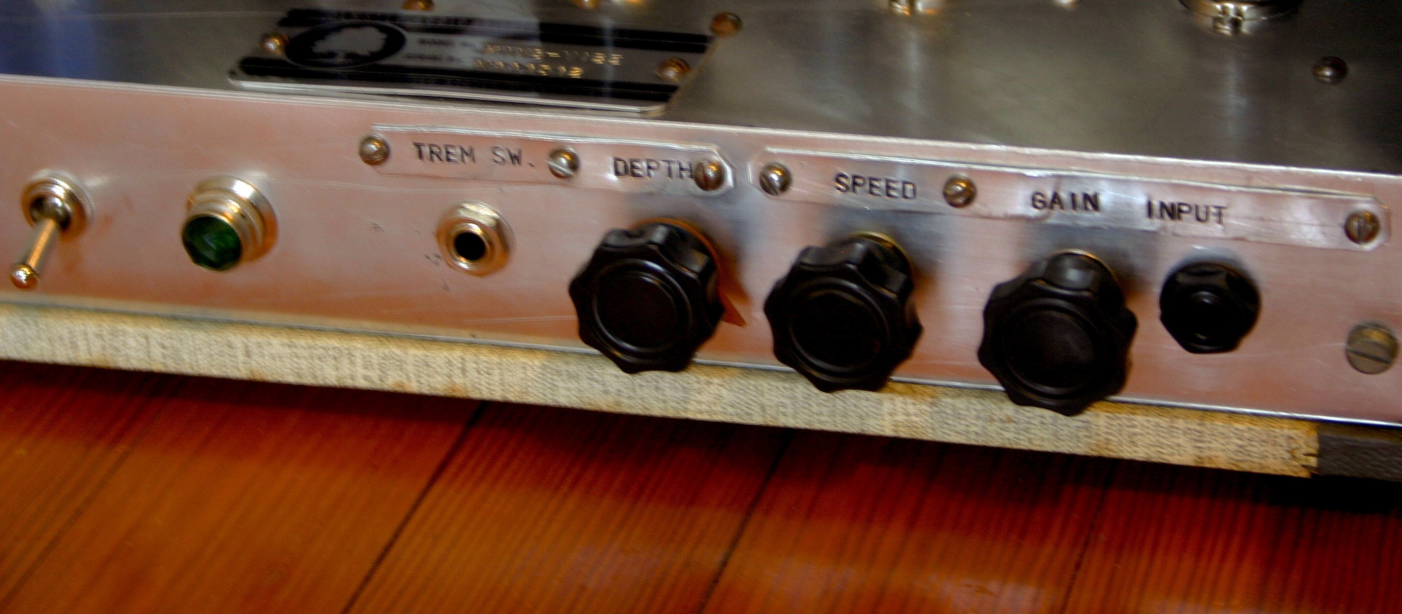
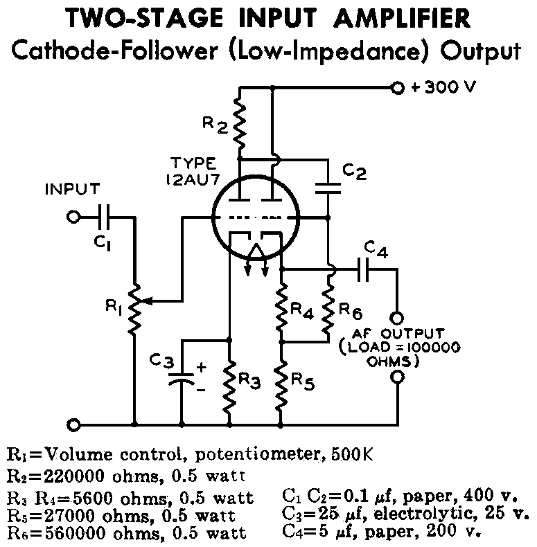
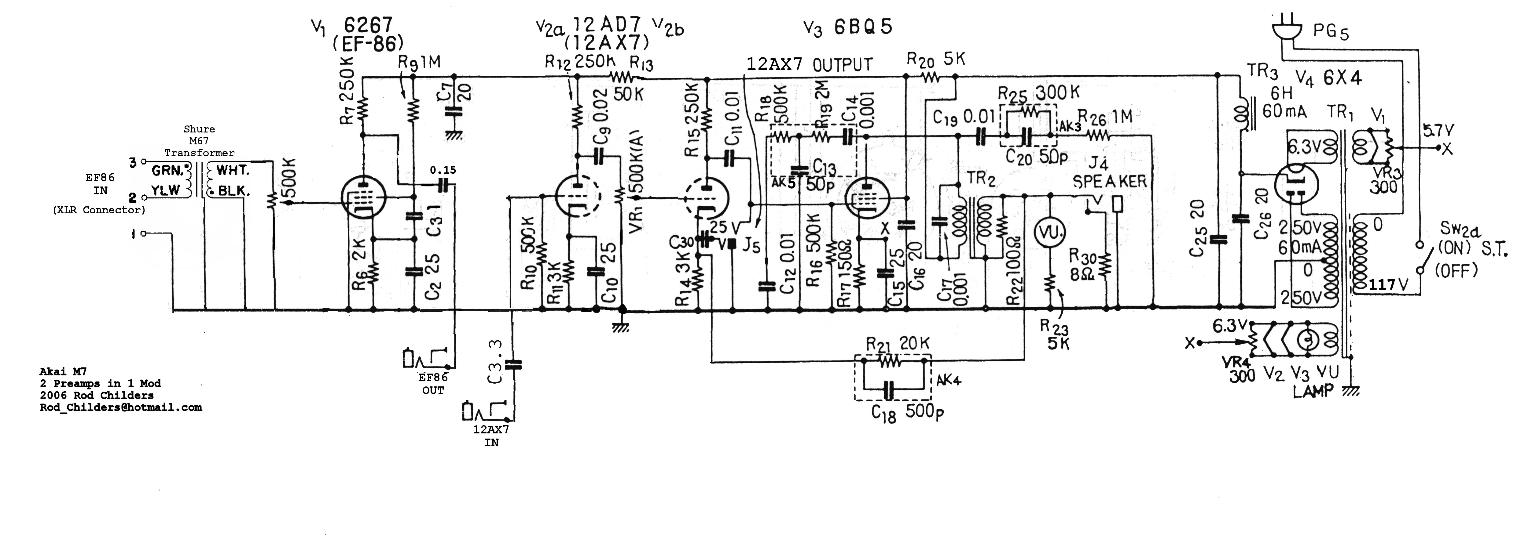
Above is the Akai preamp with the popular ‘Ron Childers’ modification notes added (I can’t seem to recall where I found this – if someone has an attribution link, pls LMK and I will add it).  I began the prototype by building it as you see here, taking the output from the cathode of V2B.  It was quickly apparent that the cathode of the 12AX7 was incapable of driving a 15K:600 output transformer to a high enough level.  The solution was to replace the entire V2A/V2B section with a 12Au7-based voltage amp plus cathode follower similar to this classic RCA design:

12AU7-Cathode-Follower-Schematic(Source)

I repo’d the gain pot between the EF86 input stage and the first stage of the 12AU7, also adding a 1/4″ switching jack immediately ahead of the pot so that medium impedance (nominal 10K ohm) signals could be ‘directly injected’ into the 12Au7 stages (ideal for adding a little bit of gain and/or crunch to drum machines and synths).   I also added phantom power and my familiar variable output pad (see here ).  The pad is fully bypass-able via the TPDT switch located directly above the pot.

AC_Custom_inside
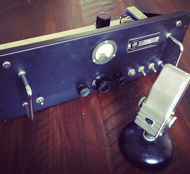
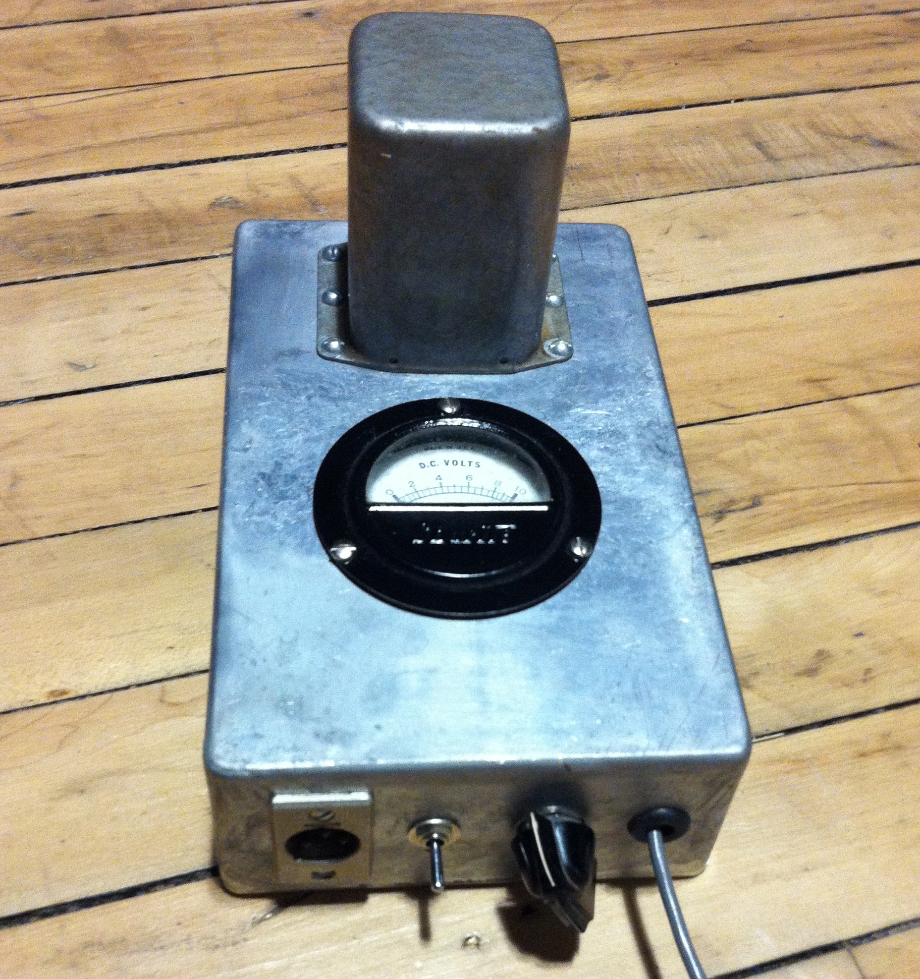
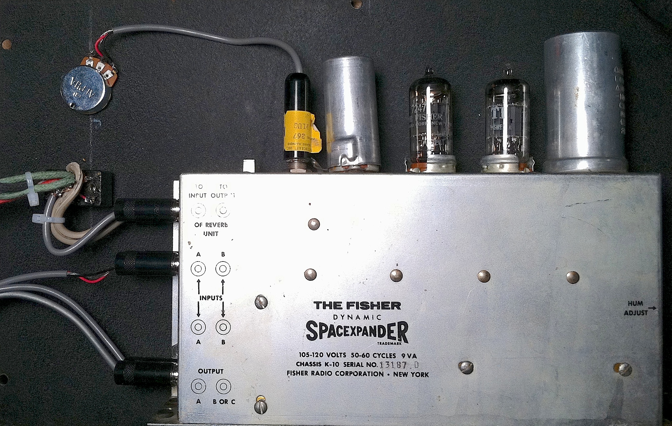
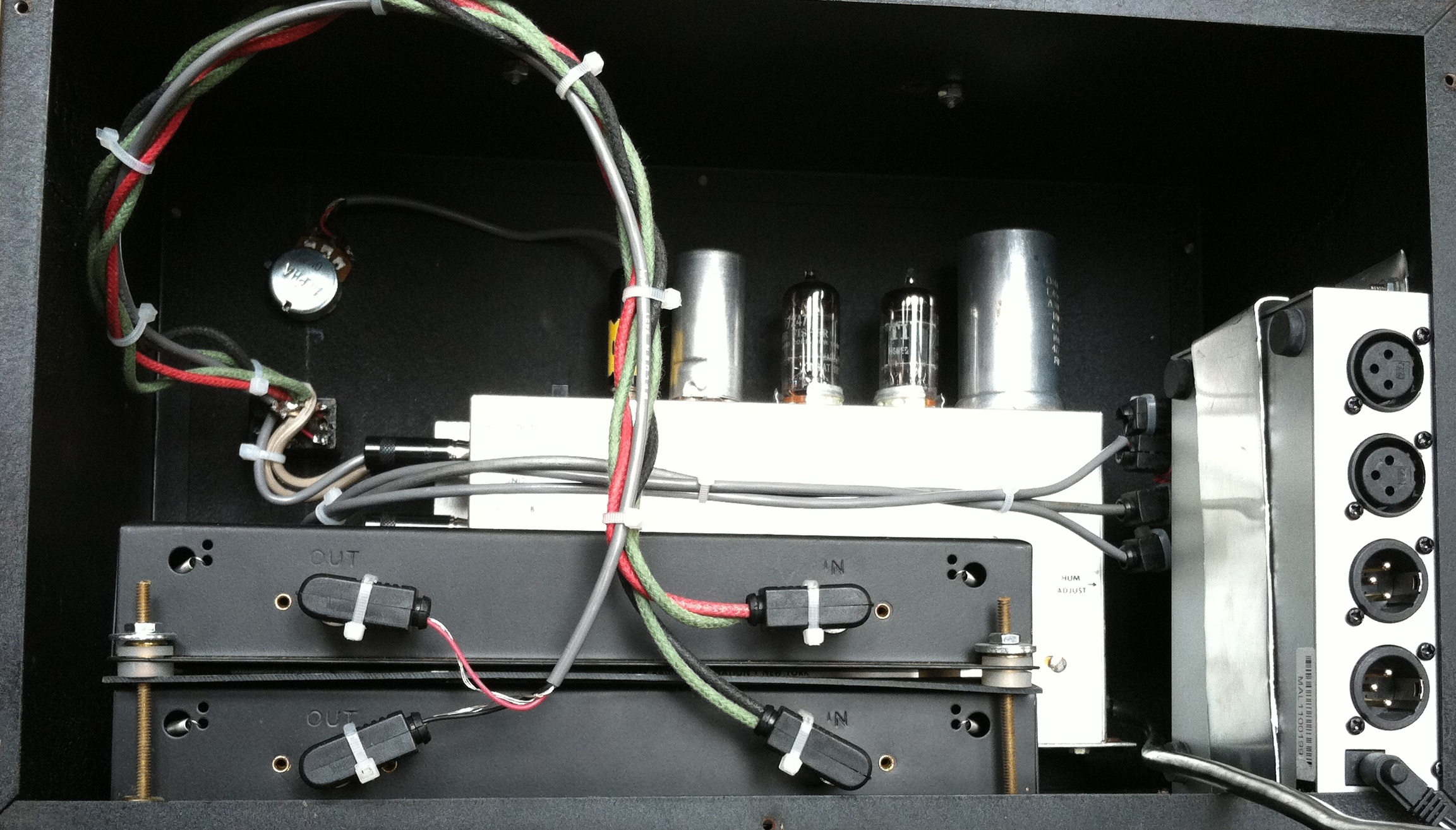
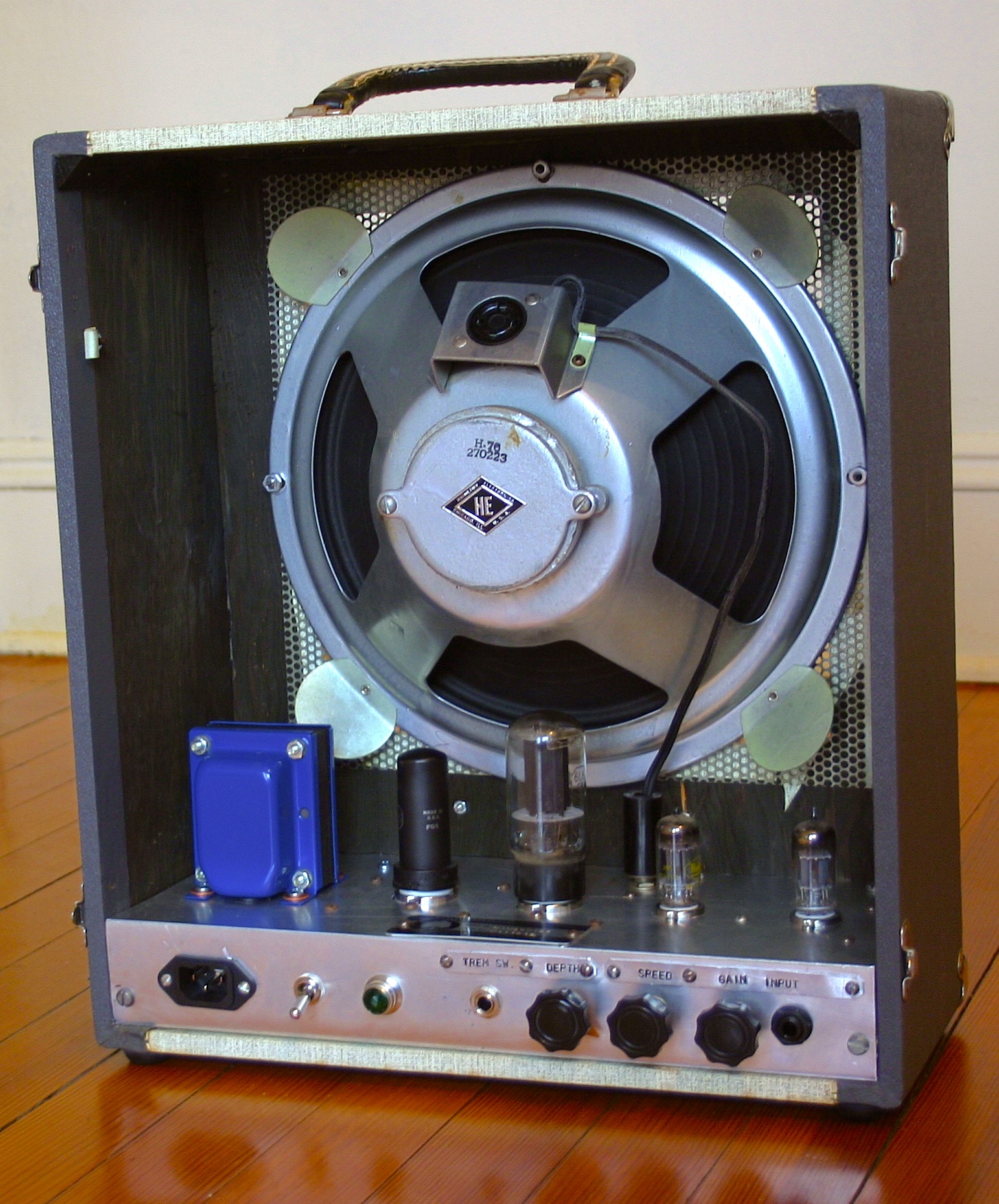
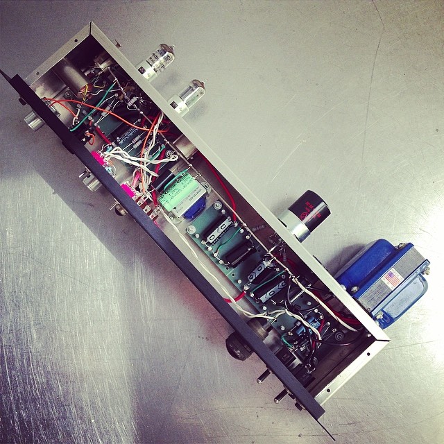
Above: inside the completed prototype

At left of the image above is input transformer.  It’s a shielded unit as found in the ubiquitous Shure M67 ‘Mic Mixer’ that was sold in huge numbers for decades to churches, civic institutions, etc.

M67(source)

Many of the online Akai/Roberts discussions recommend using the 4 input transformers as-found in these units as donors for the ‘4 channel’ mod.   Luckily I had a spare M67 in the junk pile (these things are readily available in the $10 – $50 price range) and so I pulled a transformer from it.

TWalsh_1

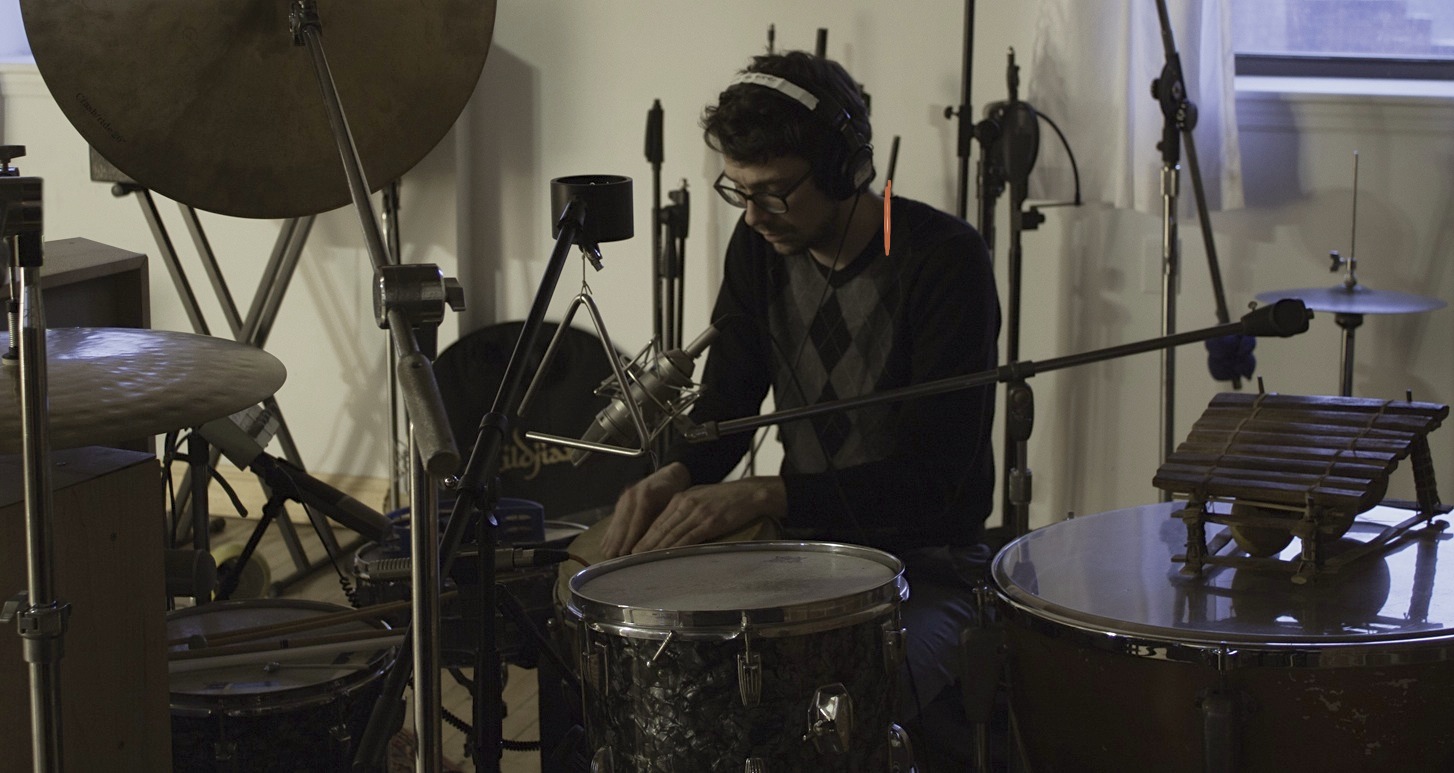
Above: T. Walsh at Gold Coast Recorders

I was pretty suspicious about the quality of these Shure transformers; even though they spec’d out OK as far as measured frequency response, I would have been much more inclined to use my standard Jensen 115 input transformer as I do in 90% of units that I build.  I thought that the best thing to do was to really put the prototype unit through it’s paces.  T. Walsh, himself an Akai machine owner, was kind enough to come to Gold Coast Recorders where we spent 3 hours writing and recording an entire pop track using only the prototype preamp on every source: drum kit (a Telefunken tube mic, in front), vocals (can’t recall,,,) , acoustic guitars (U87), hi hat (460), percussion (Royer), and all synths and drum machines were likewise routed through the front-panel input of the unit.  Here’s the track.  The lyrics are an homage to the Akai unit itself:

*************

*******

***

Categories
Custom Fabrication

Olmsted BRDCSTR preamp used heavily on latest Sigur Ros album Kveikur

Rack
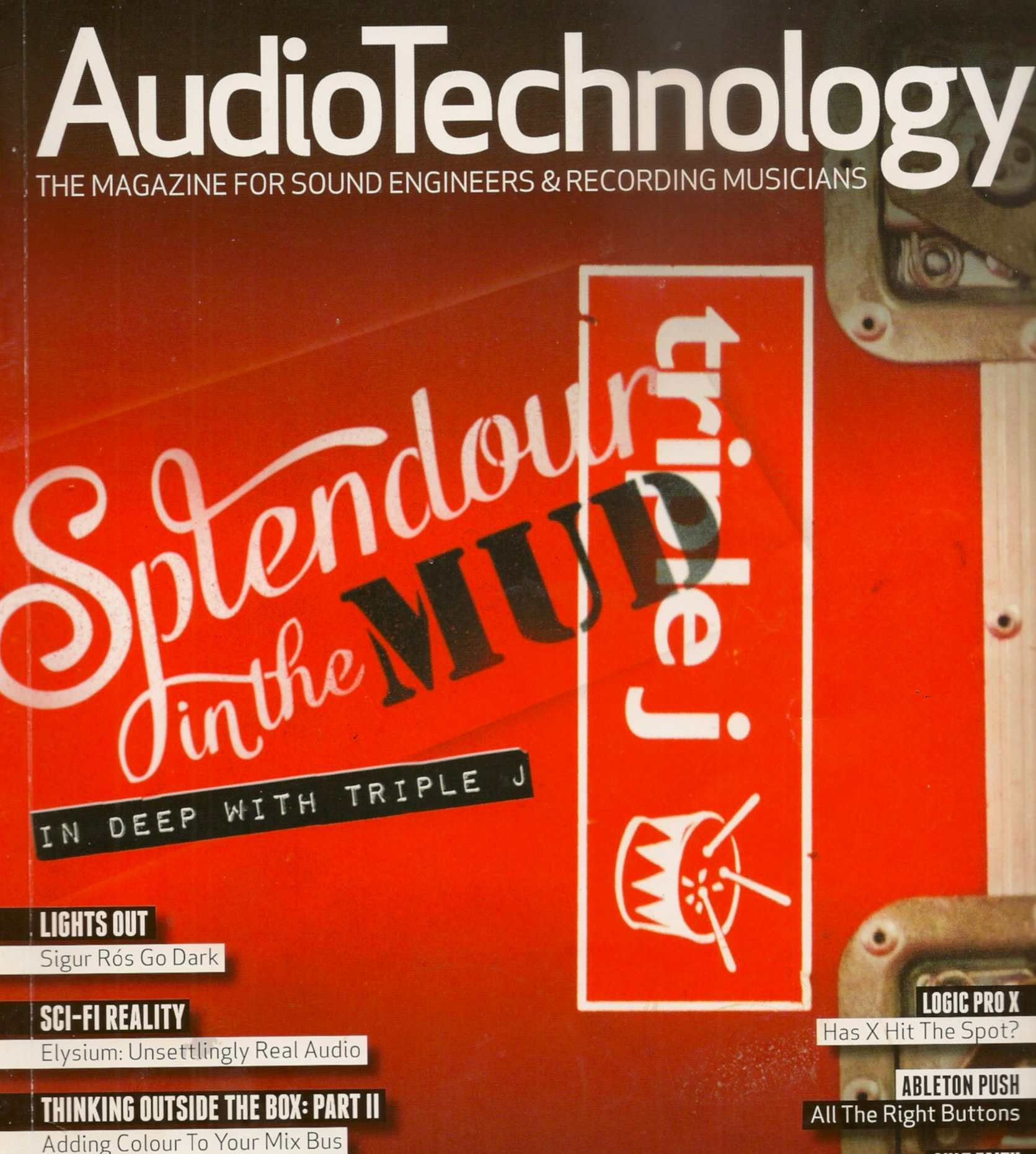
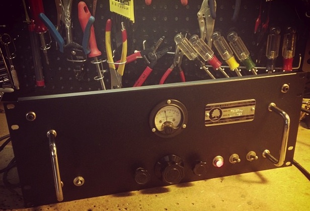
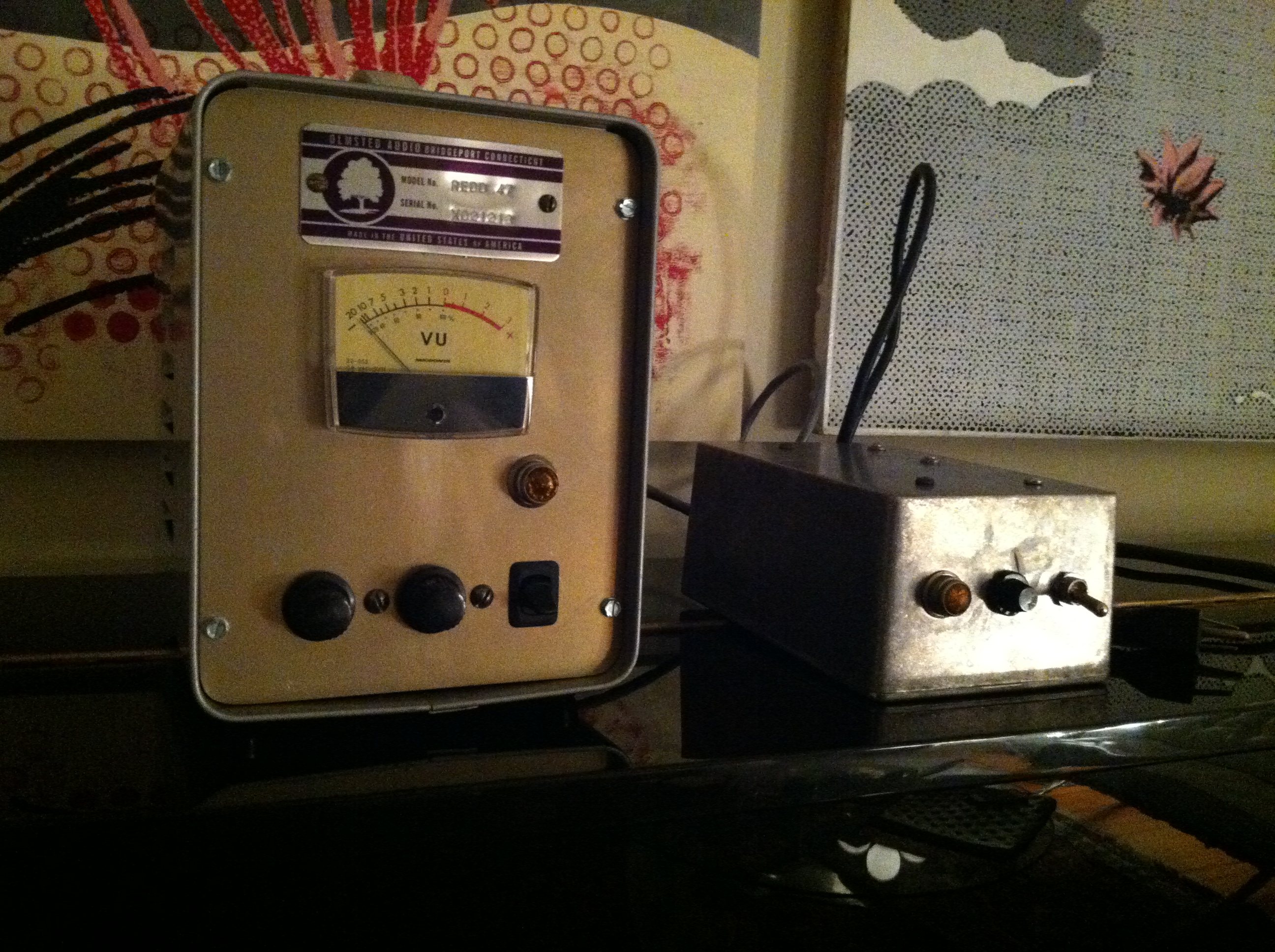
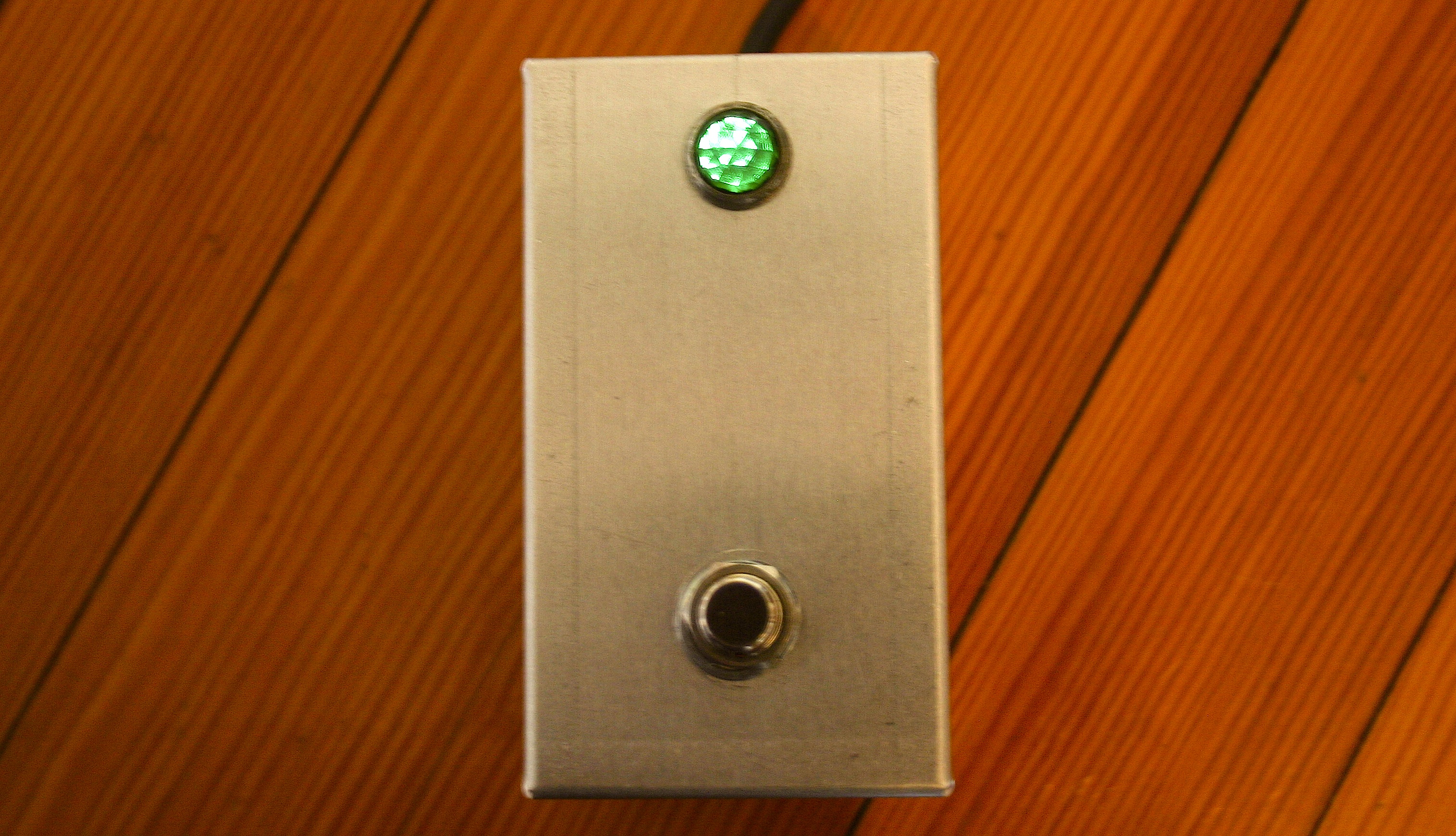
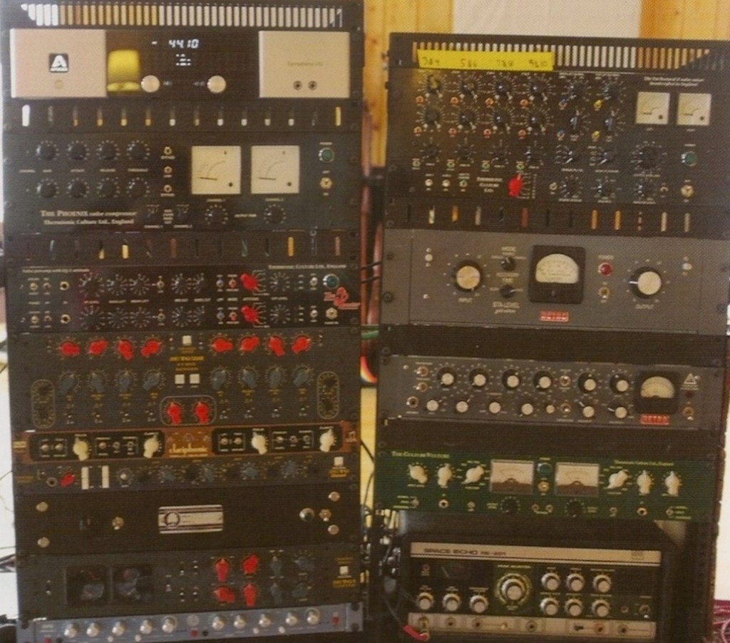
Above: the BRDCSTR in Somers’ outboard rack, left side, third from bottom

ART_coverThanks to reader EL for reporting that Sigur Ros’ engineer Alex Somers made mention of his Olmsted ‘BRDCSTR’ preamp in the Sept 2013 issue of AudioTechnology magazine.  The context was a thorough piece written by Paul Tingen on the making of Sigur Ros seventh studio LP “Kveikur.”  According to Somers,             “When recording (Sigur Ros Vocalist) Jonsi, I used a Neumann U47… we mostly used a really cool preamp made by Preservation Sound.”

See below for the full text.

Alex_SomersBelow is the actual BRDCSTR that Somers used.

Olmsted_Brdcstr_1-1024x639

Categories
Custom Fabrication Technical

Federal AM-864 Limiter Clone: Build Notes: update 1

Federal_AM864_clone_w_mic

Note: I performed extensive frequency, level, and actual studio tests on the 864 clone today, and several interesting details were revealed.  Text has been edited to reflect that. 

From 1954 through at least 1963, the Federal Television Corporation built an audio limiter called the AM 864/u for the US Air Force and US Army.  The 864 is a simple, rugged device that accepts 600 ohm balanced or unbalanced line-level signal, offers a single front-panel input-attenuator control, and compresses the output level at a 10-to-1 ratio once the threshold point is reached.  The output is also 600-ohm balanced or unbalanced, and it offers a maximum 36db of gain.  The rear panel of the unit displayed the threshold and ratio controls, although these are confusingly referred to as (respectively) CURRENT and THRESHOLD in the manual and schematic.  Attack and release times are fixed, and the manual indicates them at .05″ and 2″ respectively.

AM864_hookupAs you can see in the diagram above, the 864 was intended to be used as what we call a ‘broadcast limiter’ – the final step in the signal chain before the broadcast transmitter.

Download the original 1963 manual for the AM864 (apologies to whomever did the epic work of scanning this 55pp document; I have long forgotten where I got this file from)

DOWNLOAD: Federal-AM-864-U-Manual copy

Federal_AM864_on_benchAfter having scratch-built an Altec 436 compressor years ago, I wanted to try building an 864.  The circuits are very similar, although the 864 uses the older 1940s-era octal tubes and uses a feedback circuit from the plates of the input tubes (rather than the output tubes, as in the 436) for its compression control signal.  More importantly, though, the 436 remains a bit of an oddball underdog in the vintage-compressor market while the 864 enjoys a very strong reputation.  Anyhow, like the 436, the parts cost to build one of these things is negligible, so I figured what the hell.

This is going to be a very long + detailed +technical article, so I’m going to ask y’all to please click the link below if you dare to READ-ON,,,,

Categories
Custom Fabrication

Double Button Carbon Mic Interface/Power supply

CarbonPowerSupply2So you bought a Lifetime Model six (or some other ancient double-button carbon mic) on eBay; how the hell do you get sound out of it?  Yr prolly gonna need one of these.  A carbon mic P/S.  Allows a double-button Carbon mic to hook up to any mic preamp.

And for some examples of how these crazy mics can sound… check out these earlier posts: click here for acoustic gtr and here for drum kit

Categories
Custom Fabrication

Another Carbon Mic Power Supply

CarbonPS_TopCarbonPS_FrontHere is a one-of-a-kind unit using a re-purposed Thordarson transformer.  IT works great, and the vintage Shurite (made in New Haven CT!!!) DC voltmeter is a bonus.

CarbonPS_MeterCarbonPS_TerminalsOn the ‘business-end’ (topmost image) you can see XLR output jack (for connection to the input of your mic preamp), on/off switch, pot for controlling the DC voltage that mic receives, and at right the cable-exit for the seven-foot cable harness that connects to your double-button carbon mic.  At right: red and black wires connect one-to-each button, and the clear wire connects to the metal shell of the mic.

For an explanation of WTF this thing is, and why you might possibly need it in your life, see this previous post.

Categories
Custom Fabrication Technical

EMI Redd 47 Mic Preamp build

EMI redd 47So I was flipping through Recording The Beatles recently and I was reminded that I had yet to make one of those famous EMI console preamps.  As luck would have it, we were hit with a pretty major blizzard and I had a few days with nothing much to do.  The preamp turned out great, I love the fast (fast for a tube/transformer circuit, that it…), assertive sound of it, and I will definitely be making more of these things.  I’ve been using it primarily for tambourine (with a vintage Senn 409), acoustic slide guitar (with an Altec 660B), mandolin (with my Audio-Technica 813) and acoustic rhythm guitar and shakers (EV RE15).

Here are some of the resources that I used to build the device.  I apologize to whoever originally posted these documents for my lack of attribution; I DL’d them so so long ago that I can’t recall where they came from.

DOWNLOAD:  EMI-REDD47

Another Download:  REDD47AmpSchem

And these two images:REDD47_original REDD47

There is a real lack of consistency among these documents, and no I am not going to offer a ‘corrected’ schematic; that being said, if you actually have the where-with-all to fabricate one of these things from scratch I think you will do just fine with the same materials that I started with.  And if you don’t want to do it from scratch: no problem!  Just visit these dudes.  (n.b.: I have never used a drip electronics product personally, so I can’t vouch for them; that being said, they are extremely popular and seem to know what they are doing).

A few build notes

 I used my usual Jensen input transformer (click to DL info) and Edcor output transformer.  The thing sounds great overall, so I recommend these, at least for a first-build of this circuit.  Why spend more?

Very important: this circuit uses a lot of negative feedback. There are also a lot of capacitors in the feedback path.  Each capacitor contributes some hi-pass filtering, which should be below audio range, BUT…  if the capacitor values don’t all ‘play -nice,’ you could end up with so much phase-shift in the sub-audio region that there is 180-degree phase shift in the sub-audio region and you will have a device that ‘motorboats,’  I.E., your ‘negative feedback loop’ is a POSITIVE feedback loop aka a fkkn oscillator.  I had this problem initially.  The device worked fine, seemed to sound good, but at the lowest gain setting (aka the setting with the MOST negative feeback, get it????) I was seeing some 10hz signal pretty prominently in the audio files.  I guessed that this was due to the fact that I used a 47uf cap by the cathode of the input tube,  rather that 100uf that is specified.  I made the correction and viola problem solved.  HERE’S THE SHORT VERSION:  with this much feedback, component values are critical.  BTW, who knew that Apogee A/D convertors work so well at 10hz???

The Redd 46 has a three position gain-switch, and also a ‘gain trim’ control that does very very little.  Think of it as a ‘channel matching control’ rather than a level control.

Because of the lack of gain control, and the fairly high minimum gain setting, the Redd 46 really needs pads to be used in the studio.  Since I did not leave enough panel room to add i/o pads, I have been using it with some external 10 and 20 db ‘XLR barrel’ pads.  Depending on the amount of drive and crunch that I want in the signal, I have been adding the pad either before or after the preamp (or both!) before the signal hits the convertor.  Therefore, the next time I build one of these, I am going to include two two 3-way (0-10-20) switched pads in the device, one before the input trans and the other after the output trans.  I highly reco that you do the same.   I generally use a pad design similar to this one suggested by JLM audio; never had a problem with it.

BalPad_switched copy

EMI redd 47 with power supplyAbove: another shot of my REDD 47; the box on the right is the power supply; basic voltage-doubler (ala the Altec 1566) with tons of filtering and a choke for the B+ and DC filament supply.  Connection is by a 4-pin amphenol.

I have gotten a lot of questions regarding the enclosure used for the audio chassis:  it’s a BUDD enclosure of some type, I can’t recall the exact product name; it was dead-stock from a local distro, last one they had, and I am guessing that it was manufactured in the 70s.  No idea where to get more of them.  If you know, please drop us a line…

Categories
Custom Fabrication

The Black Box

BlackBoxLet’s just say hypothetically that you had to write+ record a tremendous amount of guitar-based music very quickly.  And even though you work at a recording studio filled with numerous custom and vintage-modified tube amps and great microphones, this music needed to be recorded in a modest home-studio using the not-awful but not-awesome Line 6 POD Pro XT.  Could there be some device that might bridge this gap in audio aesthetics, if even a bit?

NameplateI’ve used the Line 6 ‘POD’ series of devices for a decade; they are not very good for recording prominently-featured electric guitar parts, but they definitely have their uses in the studio; the Bass Pod Pro has actually worked out well a few times, and the Pod Pro is often good to add grit to synths.   When music must be recorded in a domestic environment, though, a POD can be very helpful, at least logistically.  I recently bought the newer POD ‘PRO XT’ version for around $200 on eBay.  Aside from an annoying but sonically inconsequential mechanical-hum given off by the power transformer it seems to work fine.  It even has the ability to user-adjust the blend between close mics and far mics on the ‘Amps.’   Does it sound just like a good tube amp, well-mic’d, in a great sounding room?  No.  At best, it sounds rather like playback from a 16-bit ADAT, if any of y’all can remember that sound.  Not bad, but not very detailed and overall sterile.   I knew that some tubes, transformers, and real mechanical reverb could help transform the POD sound to something that I would be a little more comfortable with.  So when I found a Fisher Space Expander for $10 at the flea market last fall, this little project went up near the top of the list.

On_PanelThe Fisher is an old home HiFi reverb system with unbalanced -10 input and outputs; I need +4 balanced.  But I did not want to modify the Fisher unit in anyway (other than adding a grounded AC lead), since they are highly sought-after and i might want to sell it someday.  So i rigged it up inside this old salvaged DIY ham-receiver case with one of those MCM electronics balancing amps, and two inexpensive Jensen MOD series 9″ reverb chambers with medium-impedance inputs (around 300 ohms, I believe).  One tank is short decay, the other is long decay.  I realize that the 17″ larger tanks do sound better, but since this box was destined for my tiny home-studio, size is a real issue; I needed everything to fit inside the 14×8″ steel box.   I’ve already enjoyed the benefits of being able to select two different tanks; on tracks that feature two electric guitar parts I am easily able to situate each in its own ‘space.’

RearHere’s a rear-view of the whole fandango.  Balancing amp is on the right; note that it is stereo, and the unit is fully wired for stereo; that being said, the fisher only generates a mono reverb signal which is then blended into the stereo direct output path; since I am using the unit for mono guitar tracks, I just use one pair of the XLRs at the moment.

PotSwitchAt left: the ‘blend’ knob, and below that a DPDT on/on switch that selects one tank versus the other.

Someone very helpfully scanned and uploaded the manual and schematic for this device; click here to download the PDF directly from them.    There are not too many surprises in the schematic, other than that  the first reverb recovery stage has a 330k plate-load resistor; this is the highest value that I have ever seen, and it failed almost immediately.  Twice.  I eventually put a 2-watt CC in place of the original 1/2 watt, and changed the adjacent coupling cap as well.   I had to replace pretty much all the B+ resistors in the unit (and several coupling and bypass caps) in order to get rid of some nasty intermittent noises; now the unit is working fine and it sounds really good!  A word of advice if you get one of these things: run the input hot, and back off on the return level.  It takes A LOT of signal before it distorts or smacks the tank, and you will be rewarded with a much-improved signal-to-noise ratio.   The MCM balancing amp has handy gain-trims that make it easy to achieve overall unity gain on the direct signal while accomplishing this goal.

Click here for some previous tube-reverb system action on PS dot com

Categories
Custom Fabrication Guitar Equipment Uncategorized

King-Vibe Amplifier

KingVibe_wPedalAs I mentioned on my Tumblr last year, I used the idle time during our annual Open Studios event to construct yet another Fender Champ-based guitar amplifier.  I had purchased a pair of unused circa 1955 suitcase-PA speakers cabinets, along with a Shure Commando mic, as a set on eBay for a few bucks with the intent of turning them into lil combo amps.

KingVibe_FrontAside from some odd shopwear/discoloration, the cabs were very solid and the original 12″ drivers sounded good.  Based on the interior space available (and the relatively low power handling of the  driver) I decided to build a variation on the classic Fender Vibrochamp.

KingVibe_rearAnd so was born the King-Vibe.  Similar in principle to a vibro-champ, the King Vibe has more power output (approx. 6 watts, courtesy of its 6L6 rather than 6V6 output section) and waaaaaaaaaaay more gain.  The additional 20db of gain was achieved by eliminating the tone stack.  The aluminum chassis was formed by hand; all wiring is point to point with Sprague and Solen coupling caps.  I used a 6X5 rectifier tube, as the Edcor power transformer has only a 6.3V haeater winding.  Output transformer is also an Edcor.   The speaker is attached via a 1/4″plug at the top of the chassis so that an external cab can be easily connected.  IEC mains socket is provided for convenience and a tidy appearance.

KingVibe_ControlsThe tremolo is still fully variable and there is a lone Gain control, no bass+treble knobs.  Whatever minor inconvenience this presents is more than justified by the insane amounts of distortion and fuzz that this thing is capable of.  And like the early Tweed Champs (which have the same topology), it cleans up perfectly by simply backing off of the gtrs volume control.  The 6L6 sees a little over 250V on its plate, which is the low end of the ‘textbook’ operating curve of that tube.  This allows the amp to break up into smooth power-stage distortion relatively quickly, which is kinda the point of these small amps anyhow.

KingVibe_Pedal_detailA detachable footswitch with a handy status-indicator jewel lamp completes this package.

Categories
Custom Fabrication

Marantz 7 Phono Pre/ Passive Line Preamp

Above: a  Marantz 7 stereo phono stage built for stand-alone use.  See this link for an earlier build of this same circuit, along with an explanation of exactly wtf a phono preamp is (for my 7 or 8 non-technical readers).

The major difference with this build is that I included a 2nd set of (passive) inputs and a volume pot.  This is to allow the user to connect both a phonograph and a 2nd line-level source, select a listening source, and control overall volume level ahead of a stereo power amp.  I also used a tube rectifier and a choke this time.  The piece sounds fantastic.

Stereo phono preamps are fairly time-consuming to build, and small differences in layout can have dramatic effect on the overall performance.  Here are a few snapshots of the process.

Hammond steel chassis, punched-out using Greenlee hand-punches

The underside of the unit following mechanical assembly

Initial wiring.  I always start with the ‘no-brainer,’ rote wiring tasks:  First, the 120AC wiring.  Followed by the B+ supply.  Followed by the Filament supply (if any; here you see the DC filament supply constructed at the left of the turrett board).  Finally, any passive audio-control wiring (the switch, pot, and Belden cable on the left). I wire up each one of these sub-assemblies and test each one; having 100% confidence that all this stuff is functioning properly makes it a lot easier to troubleshoot and vague performance issues once the piece has been fully wired.

…and done.  It’s hard to see how many components are mounted on the tube sockets, but trust me, it’s dense.  It never ceases to amaze (annoy) me how complex phono pres end up being.  The schematics look so simple!

Categories
Custom Fabrication

Olmsted Quad Direct Input Amplifier (Quad DI)

Download the specs/user-guide for the Olmsted Quad DI:

DOWNLOAD: Olmsted Quad Direct Inject

Let’s say that you have many vintage keyboards with weak output levels and often with high (10k ohm or above) output impedance.  You’d want to bring them up to modern operating levels and a low source impedance, and maybe to be able to color the sound with some grit.  Based on these parameters, here is what I developed.

The Quad DI provides up to 40db of all-tube gain with a 10db output pad to allow for either clean reproduction or heavy distortion.  The distortion is thick and smooth and has potential application for everything from electric bass to Rhodes piano to synth leads and even mix stems.  The cathode-follower output and hefty output transformers provide very solid bass; at +10 output levels bass response is absolutely flat down to 20hz. This is an all-tube unit, all the way back to the rectifier tube.  The only silicon devices are a handful of diodes in the input-stage heater-supply.  The power supply also features dual chokes, a feature of some very high-end hifi equipment which rarely (if ever?) makes it into pro audio gear.

The unit has 1/4″ TS inputs on the rear panel along with XLR outputs; the inputs are reproduced on the front panel with priority jacks:  I.E, you can keep the rear inputs permanently connected to a patchbay or a synth collection, and the front panel inputs will automatically disable the corresponding rear panel input if, say, you plug in a bass guitar to do a quick overdub.

I found this to be a very interesting piece to develop because it seems to synthesize several notable trends in modern music in one device.  First of all, the desire to be able to add grit/fuzz/overdrive to the sort of instruments that were considered best left ‘clean’ for many decades.  Sure, guitar amps have boasted of ‘overdrive channels’ since the mid seventies; but keyboard amps?  Not until recently.  Second, the prevalence of keyboards/synths in rock music in general:  not done some much in the Grunge era, back in a big way now, especially since bands like Animal Collective became the  standard-bearers of Indie.  Next, the console-less pro studio!  Not a big surprise there.  You can’t give consoles away anymore.  And, finally, lest-i-get-too-meta, the current widespread cultural appreciation of all things handmade + crafted, especially those that function through obsolete or antique technologies.  Could a similarly-functioning apparatus be strung together for the same price out of a pile of Chinese-made prosumer audio gear?  Probably.  But it probably wouldn’t sound this good or function this ergonomically.  And definitely not at 375 volts.