Categories
Custom Fabrication Technical

EMI Redd 47 Mic Preamp build

EMI redd 47So I was flipping through Recording The Beatles recently and I was reminded that I had yet to make one of those famous EMI console preamps.  As luck would have it, we were hit with a pretty major blizzard and I had a few days with nothing much to do.  The preamp turned out great, I love the fast (fast for a tube/transformer circuit, that it…), assertive sound of it, and I will definitely be making more of these things.  I’ve been using it primarily for tambourine (with a vintage Senn 409), acoustic slide guitar (with an Altec 660B), mandolin (with my Audio-Technica 813) and acoustic rhythm guitar and shakers (EV RE15).

Here are some of the resources that I used to build the device.  I apologize to whoever originally posted these documents for my lack of attribution; I DL’d them so so long ago that I can’t recall where they came from.

DOWNLOAD:  EMI-REDD47

Another Download:  REDD47AmpSchem

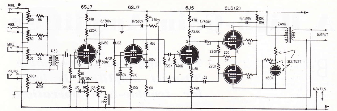
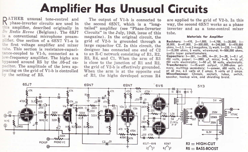
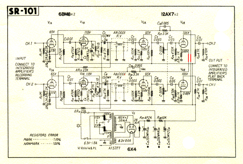
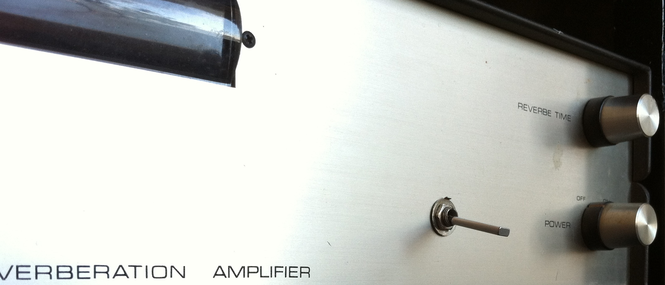
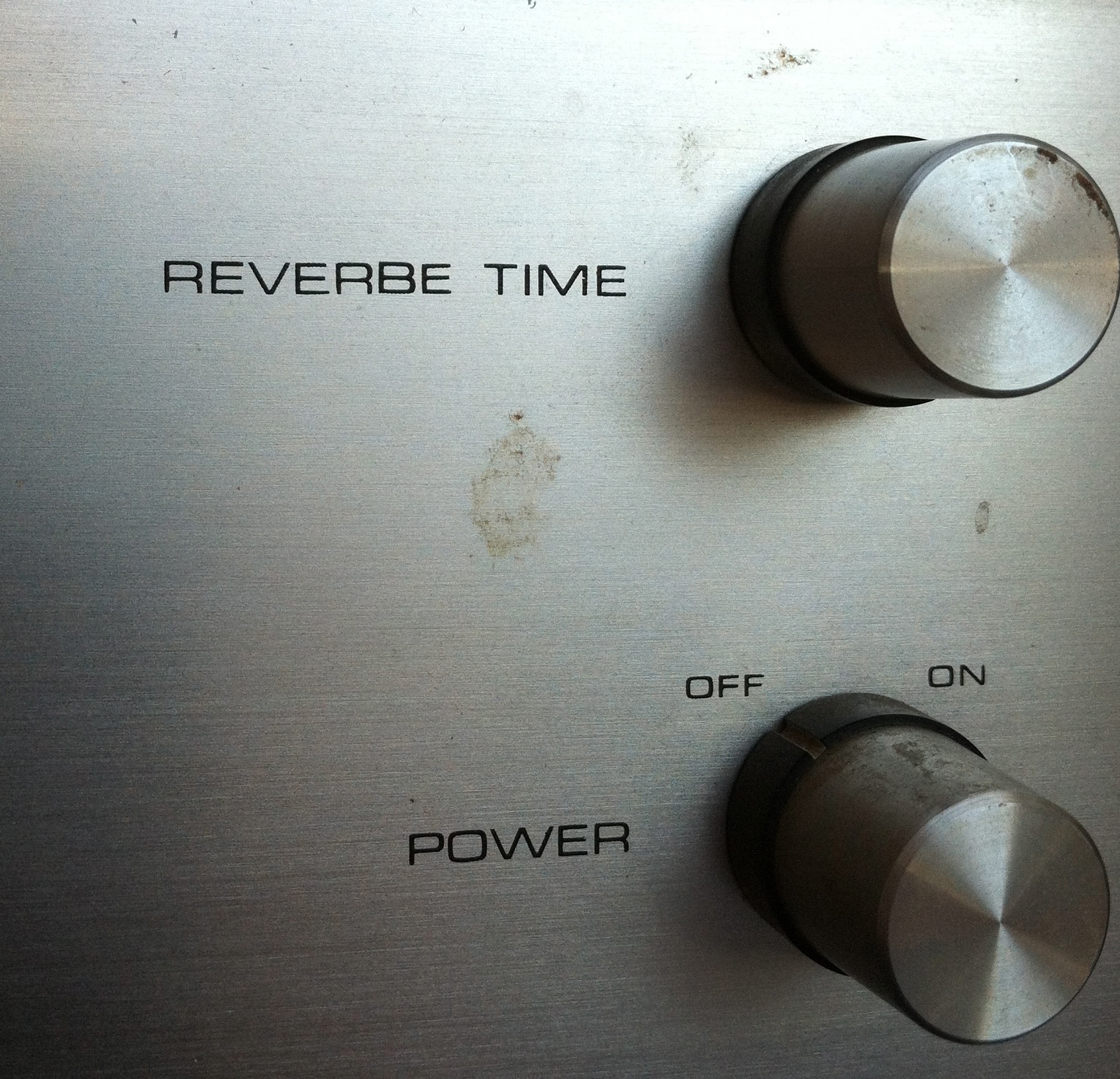
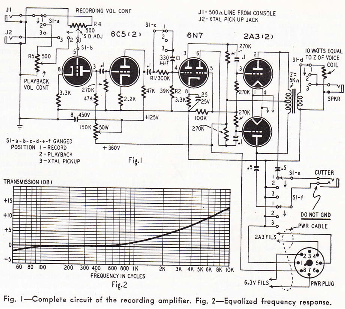
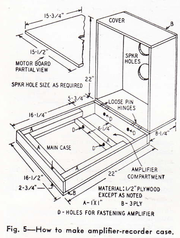
And these two images:REDD47_original REDD47

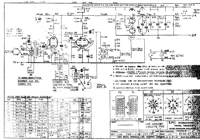
There is a real lack of consistency among these documents, and no I am not going to offer a ‘corrected’ schematic; that being said, if you actually have the where-with-all to fabricate one of these things from scratch I think you will do just fine with the same materials that I started with.  And if you don’t want to do it from scratch: no problem!  Just visit these dudes.  (n.b.: I have never used a drip electronics product personally, so I can’t vouch for them; that being said, they are extremely popular and seem to know what they are doing).

A few build notes

 I used my usual Jensen input transformer (click to DL info) and Edcor output transformer.  The thing sounds great overall, so I recommend these, at least for a first-build of this circuit.  Why spend more?

Very important: this circuit uses a lot of negative feedback. There are also a lot of capacitors in the feedback path.  Each capacitor contributes some hi-pass filtering, which should be below audio range, BUT…  if the capacitor values don’t all ‘play -nice,’ you could end up with so much phase-shift in the sub-audio region that there is 180-degree phase shift in the sub-audio region and you will have a device that ‘motorboats,’  I.E., your ‘negative feedback loop’ is a POSITIVE feedback loop aka a fkkn oscillator.  I had this problem initially.  The device worked fine, seemed to sound good, but at the lowest gain setting (aka the setting with the MOST negative feeback, get it????) I was seeing some 10hz signal pretty prominently in the audio files.  I guessed that this was due to the fact that I used a 47uf cap by the cathode of the input tube,  rather that 100uf that is specified.  I made the correction and viola problem solved.  HERE’S THE SHORT VERSION:  with this much feedback, component values are critical.  BTW, who knew that Apogee A/D convertors work so well at 10hz???

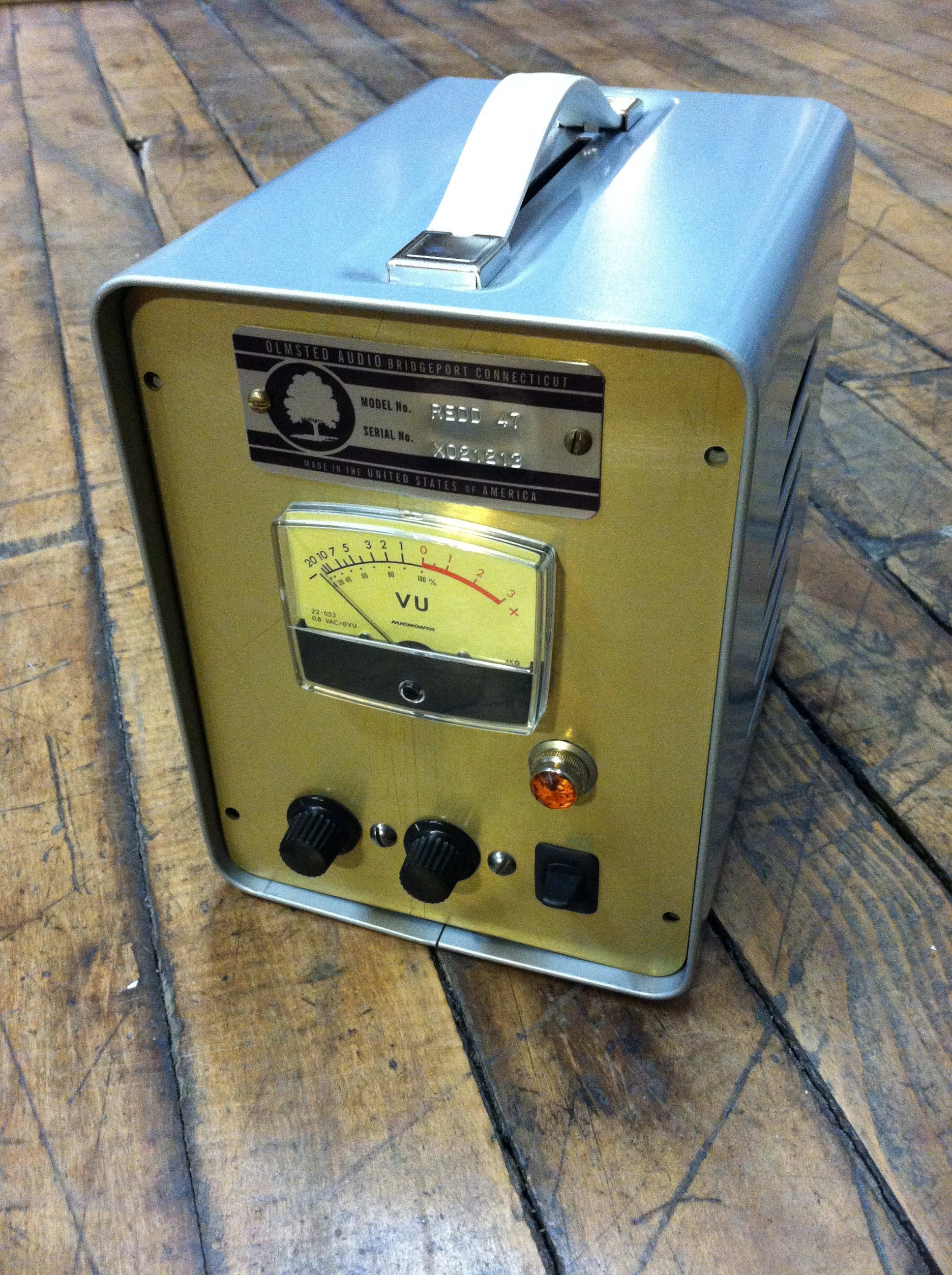
The Redd 46 has a three position gain-switch, and also a ‘gain trim’ control that does very very little.  Think of it as a ‘channel matching control’ rather than a level control.

Because of the lack of gain control, and the fairly high minimum gain setting, the Redd 46 really needs pads to be used in the studio.  Since I did not leave enough panel room to add i/o pads, I have been using it with some external 10 and 20 db ‘XLR barrel’ pads.  Depending on the amount of drive and crunch that I want in the signal, I have been adding the pad either before or after the preamp (or both!) before the signal hits the convertor.  Therefore, the next time I build one of these, I am going to include two two 3-way (0-10-20) switched pads in the device, one before the input trans and the other after the output trans.  I highly reco that you do the same.   I generally use a pad design similar to this one suggested by JLM audio; never had a problem with it.

BalPad_switched copy

EMI redd 47 with power supply
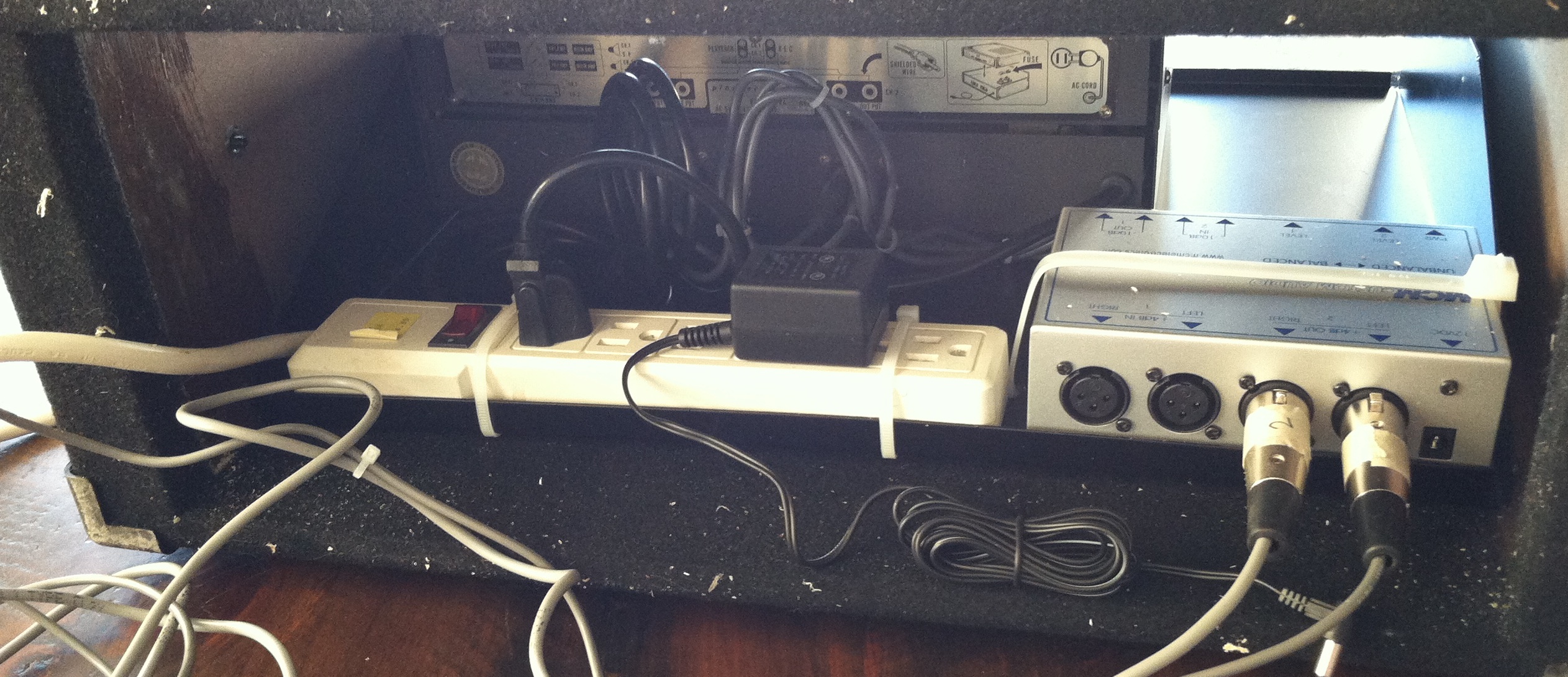
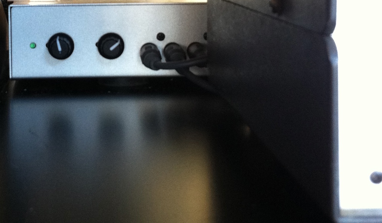
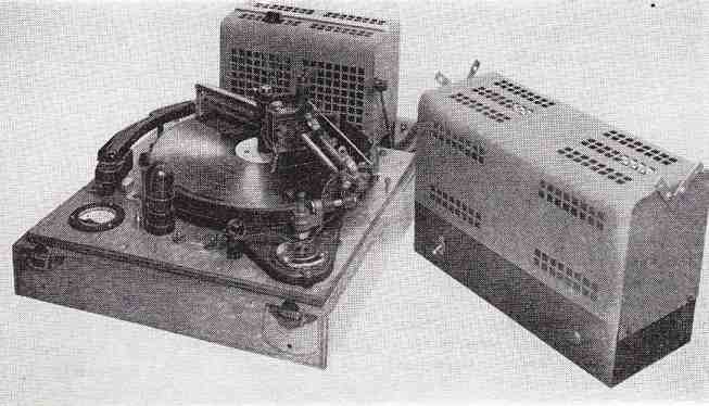
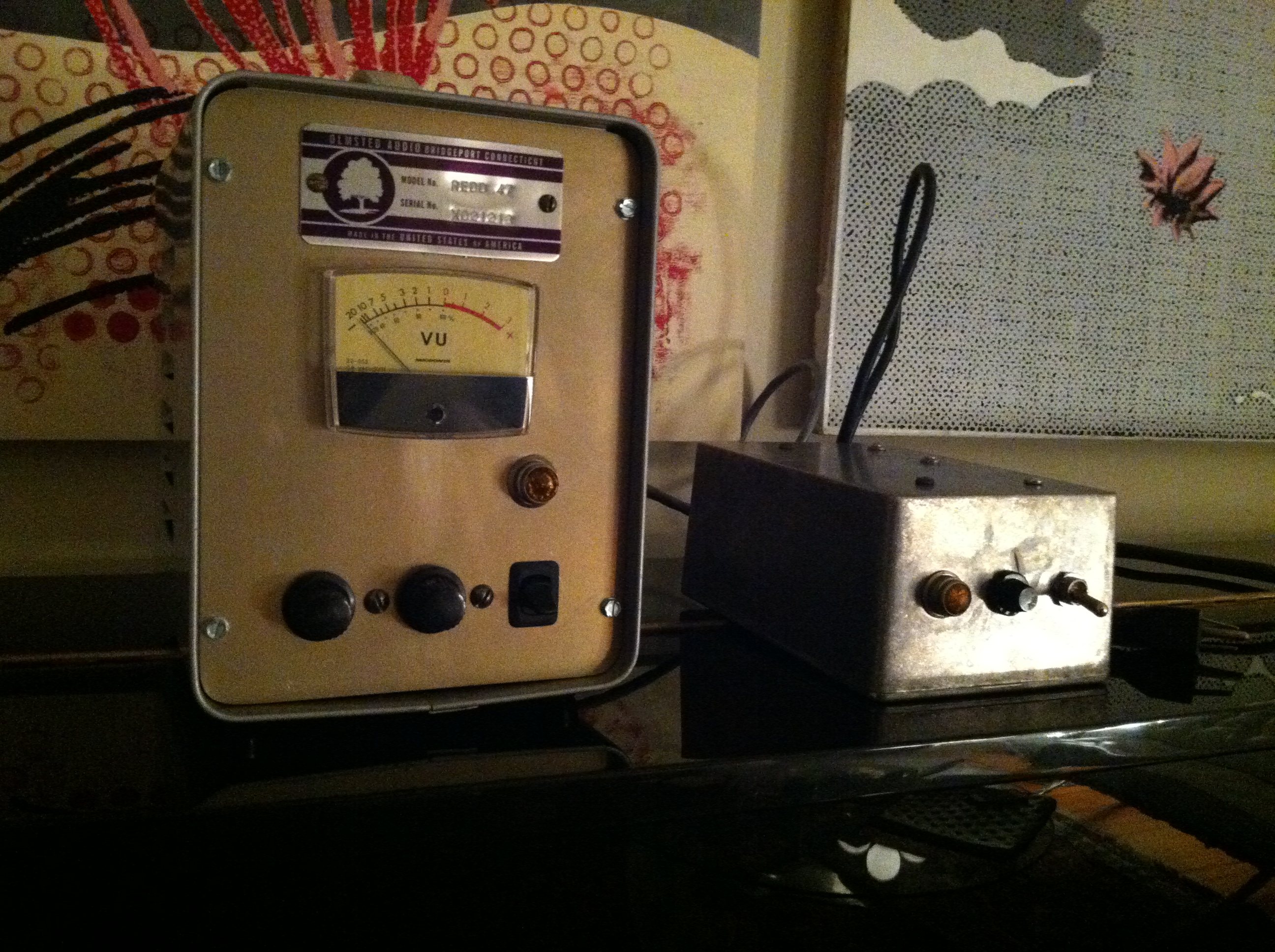
Above: another shot of my REDD 47; the box on the right is the power supply; basic voltage-doubler (ala the Altec 1566) with tons of filtering and a choke for the B+ and DC filament supply.  Connection is by a 4-pin amphenol.

I have gotten a lot of questions regarding the enclosure used for the audio chassis:  it’s a BUDD enclosure of some type, I can’t recall the exact product name; it was dead-stock from a local distro, last one they had, and I am guessing that it was manufactured in the 70s.  No idea where to get more of them.  If you know, please drop us a line…

Categories
Technical

Hi-Gain PA Amplifier Circa 1950

HiGainPA_AmpFrom Radio-Electronics, 1950, comes this circuit by one James Rundo.  Download the article by clicking here:

DOWNLOAD: HiGainPA_Amp_1950

SchematicAbove, the circuit.  The front-end is set up for very low-impedance unbalanced mics that mix through a resistor network through a single  (VERY) high ratio input transformer; so that bit is not very useful. What makes this piece of interest is the unusual tone control scheme.  See the article for the details.  Could make for a really unique guitar or studio bass amp.

Categories
Antique Hi-Fi Archive Technical

Belgian Hi Fi Amp circa 1950

PreviewScreenSnapz001PreviewScreenSnapz002From Radio-Electronics March 1950 comes this piece.  Download a PDF with high-res scans by clicking the link below:

BelgianAmp1950

Categories
Technical

Mechanically-Achieved Audio Time Compression/Expansion

DiagramFrom DB Mag, sometime mid seventies:  a really fascinating discussion of something that I would have guessed was impossible: completely electro-mechanical automated audio time compression/expansion.  As-in: changing the run time of an audio recording without changing the pitch.  The article was written by one Sidney Silver, who was the recording/audio director of the telecom division of the UN.  I feel like this could make an amazing-sounding plug-in if someone took the time to digitally model it.

Text1text2

Here is a June 1958 press announcement for Springer’s device, compete with photograph.  The price in 1955 was $1900 ($14,000 in 2013 dollars) (SOURCE)

FirefoxScreenSnapz001Do any of these ‘Acoustical Time Regulators’ survive?  Anyone ever seen one, or heard this system in operation?

For more information regarding this technology, click here.

Categories
Technical

Leon Russell’s Direct Box circa 1975

LeonRussell_DI_DB_0675From DB magazine, June 1975: a direct-box that was custom-designed for Leon Russell’s studio.  I am a huge LR fan and once I dig up a 30:600 transformer I am gonna throw one together.  Question for you solid-state guys:   2N3688 is no longer available; is there a ‘preferred’ substitute?  And: 2N3565 seems crazy expensive!  $11!  is there a cheaper sub?

Categories
Technical

Pioneer SR101 ‘Reverbe’ Unit

PioneerSR101_inCaseI picked up the above-depicted Pioneer SR-101 all-tube Stereo Reverb unit for a few dollars at the final flea of ’12.  It worked after some minor repairs and I am happy to report that it’s actually a pretty fine lil box.  I made a few modifications and added some hardware to adapt it to studio use.  I’ll describe the whole fandango here in case any of y’all are thinking of going down the hardware-analog-reverb path.  There are plenty of these things on eBay, often closing in the $50 – $200 range. Even if you have to spend a lil time or money on some repairs, it could still be a lot cheaper than the roughly comparable Orban 111B or the Sound Workshop 242, both of which we also have + love at Gold Coast Recorders.

frayedWiresAbove: the ‘pickup,’ AKA ‘output’ side of the twin tanks.  Unlike the Fisher Space Expander (which I also just picked up… deets on that one soon…), the Pioneer is a true stereo machine.  Each input feeds its own physical reverb tank.  This is a big, big benefit over the mono-summing of the Fisher.  My SR101 unit was passing direct signal, but not reverb, on one side; the culprit was actual just the output lead of the tank (above), which was over-heated during manufacture and had a signal-leak-to-ground on the coaxial cable.  A quick snip-n-solder and we’ve got SOUND.

GroundBecause this is 60’s piece, the AC mains are not grounded.  So I hacked up a nice long IEC cable and added that.  Above: I connected the ground (green) wire to the common lug of the multi-cap cap.  Seemed to be the most convenient option…       The only other repair was of a more mechanical nature.  The tanks are suspended from steel risers via small springs, with foam rubber pressed between the tanks+chassis.  45 years of tiiiiiiiiiiiime marching-on had turned much of the foam suspension into sticky goo; I replaced the rotted foam with some generic foam road-case-material.

PioneerSR101_SchemAbove: the schematic of the SR-101, courtesy of this handy web forum.  Notice the two red wires: the fellow who originally posted this schem was kind enough to highlight them.   Here’s why.  When I originally got the unit, it was a little tricky to troubleshoot; the left input came out of the left dry output, but the left channel reverb emerged from the right out.  WTF?  Turns out that this was a gimmick that Pioneer used in order to ‘widen’ the stereo effect.  And it does work, but that would just be confusing as hell in the studio.  So I re-reversed (versed?) the direct-signal wires and then reversed the leads going to the RCA output jacks.

swtichWhile I was at it, I drilled a hole in the front panel and added a DPDT on-on switch that cuts the direct signal fully out-of the signal path.  So now the left channel input and its associated reverb both emerge from the left output, as one would expect, and vice-versa for the right channel.  PLUS, now I can flick the switch up and  get reverb-only in the outputs.    Easy enough…

case_rearAbove: the rear of the rack-case.  That lil silver box on the right is a bi-directional stereo balancing amp designed to interface consumer audio gear with studio (or broadcast) audio systems.  Basically, it takes a stereo balanced +4 input signal and drops it to -10 unbalanced output, and simultaneously takes a -10 stereo input signal and boosts it to a +4 balanced output.   I own many of these sorta things, but the unit above is notable in that it is really, really, really fukkin cheap.  These things are generally in the $70 – $200 price range, but my fav purveyor of dirt-cheap electronic crap MCM electronics has em now for $39.  There are often sales too; I think I paid $35 for this one and $30 for the last one I bought.  Both worked fine BTW.  Anyway, I wouldn’t recommend that you mix a record thru the thing, but I can’t imagine it doing any harm to the signal coming from a 45-year-old box of tubes and springs and carbon-comp resistors.

balance_AmpAbove: the front of the balancing amp as seen from front of the rack-case.  The knobs set the send and return levels to and from the SR-101.  This is super-handy in terms of setting the right nominal level to ensure a good signal-to-noise ratio without creaming the tanks too hard (wow that sounds gross).  Unlike the reverb tank in a fender guitar amp, for instance, the SR-101 hits the tanks with power amp tubes (around 2 watts, as opposed to maybe 100 milliwatts in a fender).  So it is possible to get a pretty good signal level out of them without too much objectionable noise in the tank return circuit, provided that you hit the tank input hard enough.  I might be repeating myself now, sorry, it’s late…

ReverbeAnd above: the sole audio control on the unit, charmingly labeled ‘REVERBE TIME’  Yes Reverbe.  Love it.  As the schematic reveals, this is simply a passive gain control in the tank pickup amps.  So yeah it’s a one-sound box.  But it’s a glorious sound.  This dusty gem just got put in GCR today, so once I get a chance to try it on a mix I’ll post the results.

Categories
Technical

1949: Build your own Disc-Recorder!

DIY_DiscRecorder_imageDownload a four-page article from RADIO-ELECTRONICS, 4/1949, on the subject of ‘build your own disc recorder’:

DOWNLOAD: DIY_DiscRecorder1949

DR_SchemAbove: the schematic.  I can’t say that I have ever hand-built an audio unit that also required dynamic mechanical components, IE., moving parts.  Seems rather ambitious.  In 1949 the tape recorder was already becoming part of American media production, if not daily consumer life.  Disc recorders were soon to become a thing of the past.

DR_Case

Categories
Technical

Single-tube audio oscillator c. 1946

Download a four-page article from RADIO NEWS, November 1946, containing data and plans for constructing a surprisingly simple tube audio oscillator.  Author is R.W. Ehrlich.

DOWNLOAD: SimpleTubeAudioOsc

One 6SN7 tube plus a handful of caps, resistors, and pots (oh and a power supply).  12 of these would make the basis of a pretty interesting synthesizer.  I was wondering what I was gonna do with the 100000 6SN7s I have accumulated.  Why so many 6SN7s?  It’s like the Whipped Cream And Other Delights of used vacuum tubes.  At least one in every pile.

Categories
Technical

1961: Five Things

From the 1961 Langevin Catalog, which unfortunately I cannot upload due to massive file size.  Anyone know of a reliable, free way to reduce PDF size?


Categories
Altec Technical

Novel Vacuum Tube / Diode Compressor: 1950

Download a short piece from RADIO-ELECTRONICS, 1950, on the subject of a DIY audio-compressor:

DOWNLOAD: DiodeCompressor1950

This promises to be an interesting unit.  It’s designed (like a Shure Level-Loc) for Mic-Level-In, Mic-Level-Out, but that could pretty easily be changed for balanced-line operation by omitting the first 12AT7 stage and using a modest step-up transformer (maybe 1:3 or 1:5) going into the input level pot, and then adding another output stage and output transformer.  (Since 1/2 of the 2nd AT7 is unused, I am thinking: eliminate one of the 12AT7s entirely, build this circuit minus the first stage using one 12AT7, and then add the output stage from the Altec 1566).  The unit promises to add distortion, and there is some sort of low-pass network before the 3rd grid that will also need some sort of variable components added in order to control the quality of that distortion.  My biggest question, though: will plain ‘ole IN4007 Diodes work in the circuit?  I plan to build this thing soon and all questions will be answered… always looking for new (old) sources of novel grit+crunch….