Categories
Uncategorized

DIY Tube Broadcast Console c. 1964

Console_DiaFrom BROADCAST ENGINEERING Mag, circa 1964, plans by one Robert Tiffany on the design and construction of a low-cost ‘standby’ broadcast console.  Output amp stage uses my fav line output transformer, the UTC A-25: still unequaled among air-gapped plate:line transformers for low-frequency response.  BTW, add a 600:60K mic input transformer to the front of this thing and you’ve got a pretty nice mic preamp with a LOT of gain.

DOWNLOAD: Console_0001 Console_Amp_Schem

Categories
Custom Fabrication Technical

EMI Redd 47 Mic Preamp build

EMI redd 47So I was flipping through Recording The Beatles recently and I was reminded that I had yet to make one of those famous EMI console preamps.  As luck would have it, we were hit with a pretty major blizzard and I had a few days with nothing much to do.  The preamp turned out great, I love the fast (fast for a tube/transformer circuit, that it…), assertive sound of it, and I will definitely be making more of these things.  I’ve been using it primarily for tambourine (with a vintage Senn 409), acoustic slide guitar (with an Altec 660B), mandolin (with my Audio-Technica 813) and acoustic rhythm guitar and shakers (EV RE15).

Here are some of the resources that I used to build the device.  I apologize to whoever originally posted these documents for my lack of attribution; I DL’d them so so long ago that I can’t recall where they came from.

DOWNLOAD:  EMI-REDD47

Another Download:  REDD47AmpSchem

And these two images:REDD47_original REDD47

There is a real lack of consistency among these documents, and no I am not going to offer a ‘corrected’ schematic; that being said, if you actually have the where-with-all to fabricate one of these things from scratch I think you will do just fine with the same materials that I started with.  And if you don’t want to do it from scratch: no problem!  Just visit these dudes.  (n.b.: I have never used a drip electronics product personally, so I can’t vouch for them; that being said, they are extremely popular and seem to know what they are doing).

A few build notes

 I used my usual Jensen input transformer (click to DL info) and Edcor output transformer.  The thing sounds great overall, so I recommend these, at least for a first-build of this circuit.  Why spend more?

Very important: this circuit uses a lot of negative feedback. There are also a lot of capacitors in the feedback path.  Each capacitor contributes some hi-pass filtering, which should be below audio range, BUT…  if the capacitor values don’t all ‘play -nice,’ you could end up with so much phase-shift in the sub-audio region that there is 180-degree phase shift in the sub-audio region and you will have a device that ‘motorboats,’  I.E., your ‘negative feedback loop’ is a POSITIVE feedback loop aka a fkkn oscillator.  I had this problem initially.  The device worked fine, seemed to sound good, but at the lowest gain setting (aka the setting with the MOST negative feeback, get it????) I was seeing some 10hz signal pretty prominently in the audio files.  I guessed that this was due to the fact that I used a 47uf cap by the cathode of the input tube,  rather that 100uf that is specified.  I made the correction and viola problem solved.  HERE’S THE SHORT VERSION:  with this much feedback, component values are critical.  BTW, who knew that Apogee A/D convertors work so well at 10hz???

The Redd 46 has a three position gain-switch, and also a ‘gain trim’ control that does very very little.  Think of it as a ‘channel matching control’ rather than a level control.

Because of the lack of gain control, and the fairly high minimum gain setting, the Redd 46 really needs pads to be used in the studio.  Since I did not leave enough panel room to add i/o pads, I have been using it with some external 10 and 20 db ‘XLR barrel’ pads.  Depending on the amount of drive and crunch that I want in the signal, I have been adding the pad either before or after the preamp (or both!) before the signal hits the convertor.  Therefore, the next time I build one of these, I am going to include two two 3-way (0-10-20) switched pads in the device, one before the input trans and the other after the output trans.  I highly reco that you do the same.   I generally use a pad design similar to this one suggested by JLM audio; never had a problem with it.

BalPad_switched copy

EMI redd 47 with power supplyAbove: another shot of my REDD 47; the box on the right is the power supply; basic voltage-doubler (ala the Altec 1566) with tons of filtering and a choke for the B+ and DC filament supply.  Connection is by a 4-pin amphenol.

I have gotten a lot of questions regarding the enclosure used for the audio chassis:  it’s a BUDD enclosure of some type, I can’t recall the exact product name; it was dead-stock from a local distro, last one they had, and I am guessing that it was manufactured in the 70s.  No idea where to get more of them.  If you know, please drop us a line…

Categories
Pro Audio Archive

Audio Mixing Consoles circa 1959

Langevin stereo console circa 1959

Today: from the “Audio Cyclopedia,” Howard Tremaine, 1959: a quick visual survey of professional mixing consoles in service in 1959.  A PS Dot Com reader turned me on to the “Audio Cycolopedia”; many copies of this 1300ppp volume are available on Amazon and eBay starting at around $80; based on the number available, though, i feel like there’s a $1 yard-sale copy waiting for me just around the bend…  When the moment presents itself, we’ll be sure to run an Out-Of-Print-Book Report.

A Westrex console built for Todd-AO

The Westrex Portable Stereo Mixer, inside+out

RCA Stereo Console built for 20th Century Fox

A ten-channel stereo console built for the production of USAF training films

An eight-channel Western Electric console

Cinema Engineering Console with integral channel equalization.  These consoles were apparently introduced in 1951…

…as seen in this image from Radio & Television News, 1951.  We’re looking at Capitol Records’ studio in this image.

“Audio Cyclopedia” presents a range of material in an easy-to-read manner suitable for technical and non-technical persons alike; that being said, the book does not shy away from some very useful circuit data, such as the above-depicted Magnasync mixer schematic.  I have been wondering for some time what the proper way was to use a 5879 tube in triode mode: here we see:  100k plate resistor with 1K bias resistor.  Easy…

Categories
Technical

AWA (Amalgamated Wireless Australasia) Broadcast Equipment

Download a 24pp pdf with schematics and technical information regarding all AWA-brand vacuum-tube broadcast audio amplifiers circa 1967:

DOWNLOAD: ABCstudioEquipment

Big thanks to PS dot com reader E. Lorden.  E. lives in Australia and has provided us with extensive schematics and technical data on AWA broadcast-audio equipment.  AWA was the ‘RCA’ of Australia throughout much of the 20th century: they made and marketed both consumer and professional electronics equipment as well as engaging in actual broadcasting.  Due to a very protective import-taxation scheme in place in Australia until the early 1970s (as well as the high cost of shipping imported goods to that country), AWA was highly incentivized to develop its own unique line of broadcast audio equipment for the Australian market.  I have personally never seen any of these items myself, and many of the circuits are different than any US broadcast audio components that I am aware of; perhaps there is more of a Telefunken heritage to this kit.  Or perhaps it’s genuinely just unique.  Anyhow, plenty to dig into… limiters, mic preamps, power amps, etc…  Although the document is dated 1967, the circuits covered extend well back to the 1940s, judging by the types of ‘valves’ employed.

All photos in this post credited to E. Lorden

Categories
Custom Fabrication Uncategorized

The BRDCSTR

Above: The BRDCSTR, a two-stage vacuum-tube microphone preamp inspired by classic 1940s broadcast audio preamps.  Single-ended design with a 6SJ7 and 6J7 tubes, massive output transformer, and only one capacitor in the signal path.  I have built more of these than any other design; people really seem to respond to the sound.  It’s pretty much the least ‘stuff’ that you can put between a microphone and your A/D convertor.  All the attitude of ancient tube studio equipment without the hum and the noise, and with much better frequency response.

Categories
Custom Fabrication Technical

The Old ’76

My latest microphone preamp design is completed and sounding very cool… The Old ’76.

The Old ’76 is a novel three-stage design; it’s not based on any past or current production microphone preamp.  That being said, the circuit is nothing revolutionary: an input transformer (in this case a UTC O-1, as I was temporarily out of Jensen 115s) connects to an RCA 76 tube, biased in textbook (or, at least, RCA-Receiving-Tube-Manual-book) fashion; volume pot follows and then on to a 6SL7 tube with the first stage plate directly coupled to the grid of triode 2; the output is a cathode follower with a Solen cap and onto an Edcor output transformer.   The pushbutton switch (with associated pilot lamp) activates 48V phantom power.  Overall gain is approx. 60db and response is flat 50hz – 18khz.  I am betting that the slight high and low end roll off is due to the UTC O-1; the next build will use my customary Jensen input transformer and we should see 25hz-20khz flat response.

76 tubes were often used in ancient console radios with a large tubular shield positioned around them; the reason for this became quiet clear once I had finished my piece; before I added the above-depicted aluminum plate between the 76 and 6SL7, I was getting some unpleasant ringing on very high frequencies.

I had wanted to build a mic pre with some of these very old two-digit designation tubes for some time now.  Hi-Fi fans seem to love the 76 tube, so I figured there was probably something worth investigating.  76 tubes are readily available and pretty inexpensive; it is a bit of a challenge to find the 5-pin bases that they require though.  AES sells only one 5-pin base, and it’s expensive and oversized.  My prototype unit here used an older Amphenol socket that I dug up somewhere.

Some other miscellaneous design notes: B+ rectifier is a 6×5 tube; hammond 15mh choke was used in the B+ chain; DC filaments, as usual; the phantom power supply has a slow ramp-up when activated; the three-pole phantom switch 1)connects the 48v supply to the main power supply; 2)connects the phantom indicator lamp to the 6v supply; and 3) connects the 48v to 6.8k resistors that actually connect to the mic input jack.  I find a three-pole switch necessary in these instances because there is some ‘drain’ time involved when phantom is turned off, even with a bleeder resistor; disconnecting the 48v right before it hits the mic jack provides 100% assurance that you (I) won’t melt that BK5 ribbon (again).

An A/B test of The Old ’76 vs. the usual API 512 will be posted here in the next month or so.


Categories
Pro Audio Archive Uncategorized

UDPATED (4): Presto Recording Corp: Pioneers of ‘Instant’ Analog Disc Recording

Download the fifty-page 1940 PRESTO RECORDING CORP catalog:

DOWNLOAD (part 1): Presto_1940_Cat_1

DOWNLOAD (part 2):Presto_1940_cat_2

Products covered, with text, some specs, and photos, include: Presto Model A, Model B, Model F recording installations; Presto Model C, Model Y, and Model K portable recorders; Presto type 8-A, 8-B, 28-A, 6-D, 6-E, 6-F, 26-B, 75-A, 75-B, 75-C, 9-A, and 9-B  recording turntables; Type 62-A transcription turntable; Automatic Equalizer 160; blower system 400; 150 and 151 pickups; Microphone Mixer type 130-A, B, C; Preamplifier type 40-A and 40-B; Presto radio tuner 50-A and 50-B; Recording Amplifiers  85-A, B, 85-E, 87-A and 87-B; plus a range of parts and accessories including Green Seal discs, Orange Seal discs, and Blue Label discs.

Above, the Presto Model A, their top-of-the-line system circa 1940.

Presto Recording Corp was a pioneer of coated-disc ‘Instantaneous Recording.’  From 1933 through the end of WWII, Presto was the US leader in providing high-quality recording equipment to broadcasters, schools, studios, and government.  There is a detailed history of the Presto Corp provided at this website, so no need to re-tread those waters.  Basically, what Presto offered was a way to make good-sounding LP and 78 recordings that could be played back instantly on any home turntable.  Unlike earlier commercial recording technologies, there was no intermediate submaster required.  Presto was able to do this by having designed an aluminum (later, glass) disc that was coated with a special cellulose-based compound (featuring 51 ingredients!).

At right, the Presto 200-A Electronics package.  This was a complete system of microphone preamps, cutting amps, patchbay, and AM radio tuner that was designed to accompany the Model-A pictured above.  Presto’s ‘instant-disc’ technology was basically rendered obsolete by the development of magnetic tape recorders in the late 1940s, most notably, AMPEX (and to lesser degree, Magnecord).   The specs for the better Presto systems weren’t awful: 50-8000hz frequency range, 50db signal-to-noise ratio; but this paled in comparison to the German Magnetophon technology that AMPEX built on, with a high-frequency response to 15,000hz.

On a more basic user-level: you could always record-over a piece of magnetic tape; but cutting into a lacquer-coated disc (at $16/unit in today’s money) was a commitment.

Presto Model C, their top-end portable system of 1940 ($20,000 in 2011 dollars; 138 lbs)

Looking through this catalog, the most fascinating aspect is the large range of mechanical devices and accessories recommended to insure the fidelity of the audio.  Nowadays almost all audio control happens electronically; once the room is treated and the microphone carefully placed, our work as recording engineers leaves the realm of physical manipulation and enters a world of electronic control.  In the era of analog disc recording, though, a careful recording engineer needed blowers…

…to efficiently remove the bits of cellulose material that the cutting needle carved out the the recording blanks;

viscous-oil-filled dampers to regulate vertical movement of the cutting head (a mechanical audio compressor, I would imagine);

…an optical microscope to examine the grooves that you just cut for quality-control purposes…

fresh sharp needles to do the actual cutting work…and, if you wanted the ultimate in convenience, an ‘automatic equalizer’ to automatically boost the treble frequencies as the cutting head moved closer to the center of the disc (since discs spin at a constant rate, as the needle gets closer to the center of the disc, the actual linear speed of the needle relative to the surface medium gets slower, and as we know well in all types of analog recording, slower equals less high-end).

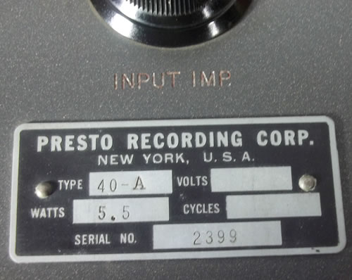
Above, the Presto 40-A microphone pre-amplifier, the one piece of equipment in this lengthy catalog that could still be of potential use to modern recordists.  It uses two 1221 tubes to deliver 55dbs of gain (from what I can gather, 1221s are interchangeable with 6C6, the 6C6 being the predecessor to the 6J7, likely making these 40As likely very similar to RCA BA1/2/11 series mic preamps).  If anyone has the schematic to the Presto 40 mic preamp, please send it to us…  coincidentally I built a preamp with 6C6s a few years ago (based on a schematic from an ancient UTC catalog) and I liked the results.

UDPATE:

Thank-you to reader EL for sending us the schem to the Presto 40-A.  Here ’tis as a download: PRESTO Type 40-A preamp schematic

…And here as well:

This must be a slightly later version of the 40-A, as the 2nd tube is a 6SJ7, which is a variant of the 6J7 that has the input grid connection in the base rather than on the top.  Other things to note: the input transformer spec’d is an ‘LS-10,’ which I can only assume means the UTC LS-10…  circuit-wise, we have the first 6J7 connected in pentode, coupled by a .1uf cap to the 2nd 6SJ7 stage, this time wired in Triode in order to more easily drive the output transformer.  A ’50M’ resistor (or as we know them, 50K ohms) provides negative feedback from stage 2 to stage one.  Thinking that this circuit could be nice as the back end to a 3-stage pre, maybe with a something low-gain like a 76 or 6J5 on the front end with a volume pot following.

UPDATE (2)

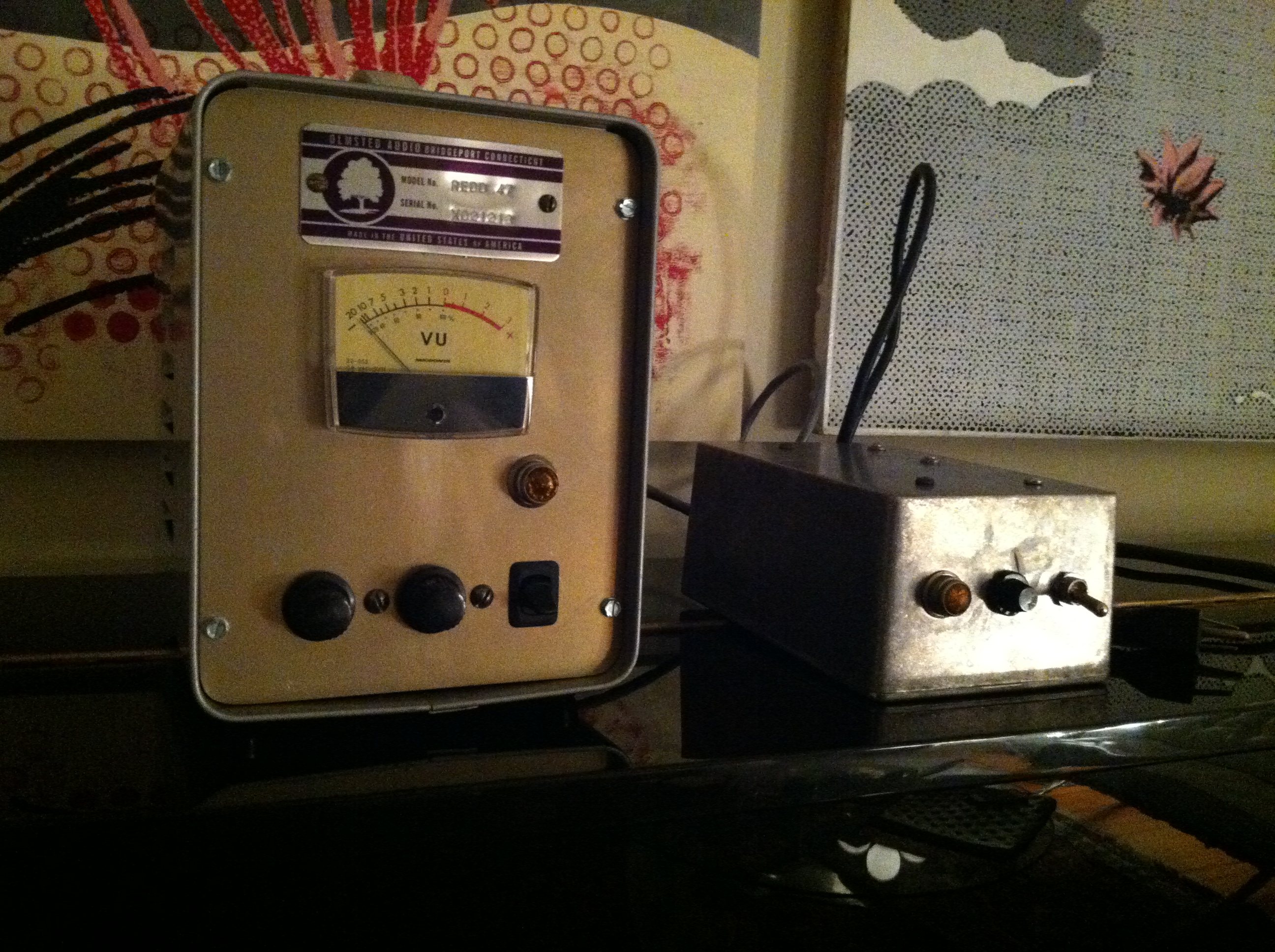
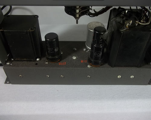
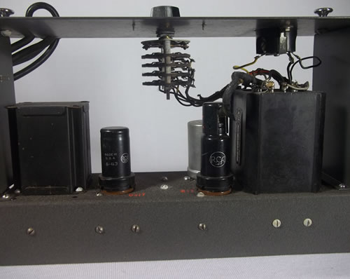
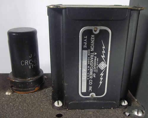
EL also provided some images of his particular 40A units… check ’em out…

Pretty amazing that these things made it all the way to Australia way back when… my lord can you imagine how much these things must have cost in their day?

***********

*******

***

*

*************

*******

***

Update Sept 2013:

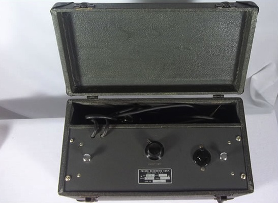
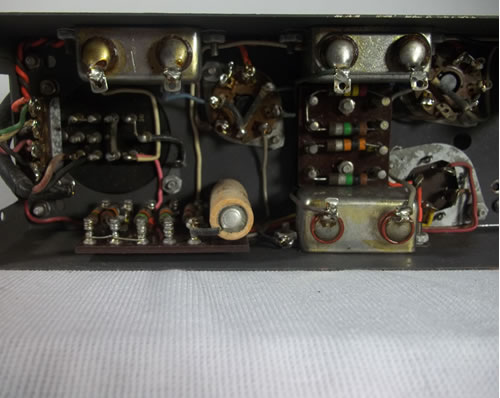
E.L. directed us to this eBay auction; a Presto 40a in nice condition (Nashville, TN) sold for $510.  Here are some images:

Presto_case

Presto_circuit Presto_inside2 Presto_Interior1 Presto_label Presto_output_trans************

*******

***

Anyone out there using any Presto equipment in their work?  Drop a line and tell us about it….

 UPDATE: a friend has alerted us to The 78 project, a series of new recordings of notable musicians made using just a Shure 51 mic and a Presto disc recorder.  They sound great, and in the videos you can hear both the modern production-sound of the session via the camera audio-track and the actual 78 playback.  Very interesting contrast…
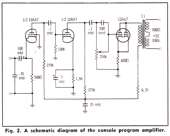
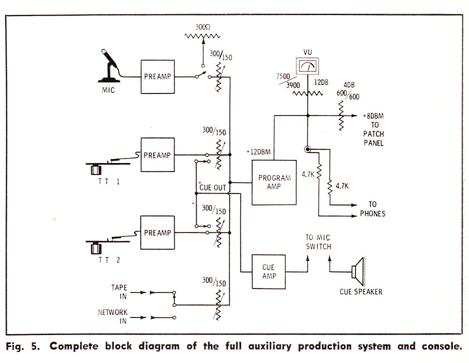
 

Categories
Custom Fabrication Gold Coast Recorders Technical

RCA OP-6/BA-2 Hybrid Mic Pre Amp: Listening Test/Shootout

Alright!  So earlier this week I described the successful completion of the RCA OP-6/BA-2 microphone preamp.  Check out this previous post for all the construction and technical details.   The short story is: the RCA OP-6 is one of the most fetishized vintage mic preamps out there; I have always wanted to try one out; the easiest/cheapest way for me to do this was to build one (or at least as close as I could get).  The problem is that the input stage requires a special attenuator device, exact values unknown; therefore I had to substitute an input stage from another device.  I chose the input stage from the RCA BA-2, as I have built many of these and they always work great.  The result: a hybrid of the OP-6 and the BA-2.

OK so there it is.  Anyway, the very helpful+generous TW came by to help me out on this one.  I wanted to try the OP-6/BA-2 Hybrid (hf. OBH) on a couple of different sources with a couple different types of mics. We a/b’d the OBH with an API 512.  I use the API 512 as a benchmark for mic-pre shootouts because it’s a high-quality unit that many people own and use regularly.  What you are about to hear are identical mics tracked through the two different preamps, direct to Pro Tools via a Lynx Aurora.  Levels were matched. No other processing, level adjustment, or manipulation was done.  You are hearing exactly what came out of the preamps.  To appreciate the differences between the units, you will need to listen to these files on good headphones or a full-range speaker system.   If you listen on a system with a subwoofer (we used the Blue Sky system at Gold Cost Recorders), you will hear some dramatic differences.

OK.  So first up: let’s listen to the drum kit above.  These are vintage ludwig drums, 30″ kick, 12″ and 14″ toms, 14×5 wood snare.  Cymbals are fairly dark old Zildjans.    You are hearing two identical Shure SM-81s placed right next to each other, approx 8 feet in front of the kit, pointed directly at the kit.  The 10db pads on the SM81s are engaged.  The SM81 is not the prettiest sounding mic, but they have a very flat frequency response.

First: here’s the API 512:

LISTEN: Drums_API

…and here’s the OBH:

LISTEN: Drums_RCA_hybrid

Our impressions were as follows: the OBH has more low end extension.  On the Blue Sky system, the kick drum in the OBH signal moved the room in a way that the API simply could not.  The API seemed to move the kit a little closer to the plane of the speakers, but at the same time the top end was not as in-focus.  There is a definite low-midrange boost going on with the API.  I can say this with relative confidence because I measured the frequency response of the OBH and it is totally flat from 15Hz – 10K, with only a very slight raise above 10K.  In terms of operation: the API gain control was at 3 o’clock; the OBH was at 9 o’clock.  WOW that is a lot of gain.

Next, let’s listen to some acoustic guitar.  TW played an old Martin D-19 (same as a D-18) that i mic’d with a well-matched old pair of Beyer M260s ribbon mics. The M260 has a built-in gentle roll off that starts at around 200hz

Alright so take a listen.  First, the API 512:

LISTEN: AcGtr_API

…and now the OBH:

LISTEN: AcGtr_RCA_Hybrid

Our impressions were that the OBH had more low bass but less low mids; it had a more ‘mellow’ feeling.  The OBH also had better high-end extension.   This also resulted in slightly more HVAC (air conditioning) room noise in the OBH.  Although I like the sound of the OBH again here, it is less of a clear-cut choice.  The mid-boost that API seems to deliver is very welcome in this particular setup.

In summary: TW put it this way: ‘(the OBH) is like a pair of gentle shelves (shelving EQs) on the very highs a lows.’  I think this is very accurate.  The OBH seems to give what I think of as an English sound: that sort of larger-than-life, hyper-real sound that UK records have always aspired to.  I highly encourage your DIY’ers out there to give this project a shot; you will find it to be a very useful tool.

Thanks again to TW for his help with this listening test; T’s band THE STEPKIDS is just back from LA where they did a direct-to-vinyl (!) live set in front of a studio audience (!!!) at Capsule Mastering Labs.  Check out the details of this very cool endeavor here and here.


Categories
RCA Technical

Building an (almost) RCA OP6 Mic Preamp

(image source)

The RCA OP-6 ‘Portable Amplifier’ is one of a handful of truly visually-iconic vintage mic preamps.   The OP-6 was designed as a “remote,” as-in, ‘on-location’ single-channel mic preamp for radio station broadcasts.  It uses three 1620 (6J7) tubes  – most mic pre designs of the period use two.  Furthermore, the 1620s are in pentode operation rather than triode.  The result: a ton of gain.  95db, apparently.  This is almost twice as much gain as the classic RCA BA1 and BA2 mic pres.  OP-6s are in high demand – click here for a seller asking $2900.   Further indication: Blackbird Rentals in Nashville has thirteen in stock as rental units.  The first time I heard an OP-6 in use was at Blackbird; I was producing/directing a live-in-the-studio performance for Martina McBride and John McBride was engineering; he was using the OP-6 for something… I can’t remember what exactly. Anyway, it caught my eye and we talked about it a bit; later I learned that he has an especially strong appreciation for these units.  A strong endorsement coming from the man who likely owns more vintage pro audio gear than anyone who ever has or ever will live.

The OP-6 schematic is pictured above (this file is readily available in high-res on the internet).  So anyhow, if we consider how in-demand the OP-6 is, it seems striking that no one offers a modern equivalent for sale, even on a small-scale level.  If you take a close look at the circuit, the reasons become apparent.  There are two big obstacles to re-creating even a semblance of an OP-6.  First is the input attenuator:

Sure, it’s a voltage divider; probably constant impedance; but what exactly are the values?  And what about that value of that feedback path issuing from the attenuator back to the input stage?  If I could get my hands on an original OP-6 and open up the attenuator, sure I could maybe sort it out.  But I imagine that re-creating that part on custom order could cost hundreds of dollars; frankly I have no idea.

The second obstacle to re-creating the OP-6 is the output stage choke.

The choke is designated L-1 in the schematic.  Curiously enough, it’s actually physically part of the output transformer.  Based on this fact, there is zero chance that this was an off-the-shelf choke, say a UTC for example, that we could track down.  OK – but the crucial value of a choke in a circuit like this is the inductance.  So long as the voltage an current handling values are sufficient, any choke of same inductance should give a similar result.  Now again, if I had an original OP-6, I could measure the inductance and maybe a current off-the-shelf part exists to satisfy the requirements.  But… I don’t think anyone out there is gonna send me their prized OP-6 to open up.  And $2900 is a pretty stiff R+D cost.  So what do we do?  Well, in the absence of any actual electrical engineering training, I looked for some good advice and then I guessed.

The very friendly+talented John Atwood sent me the diagram above; in response to what I can’t recall. This diagram explains why the choke is necessary in order to get the best possible performance from a single-ended vacuum tube line output stage.   Looks pretty similar to our OP-6 output stage, right?  Based on this… I made a wild guess.  I ordered the very inexpensive Hammond 156C choke.  150mh inductance with 8ma current capacity.  8ma might be a little low, but I have found that Hammond really undersells the specs of their transformers, so I’m not worried.

Alright so now we’ve got a choke that might work.  What about that input attenuator?  The best course of action would probably be to get a used 100k Daven T-pad, but without implementing the feedback path that the stock OP-6 attenuator has, it seems like this is slightly pointless vis-a-vis maintaining originality.  So instead: I used the input stage from my favorite, yes yet again, the RCA BA-2.

The BA-2 schematic is pictured above. The input stage uses a 1620 tube, wired as a triode, with a 100k ohm pot following it.  So I just took this input stage, up to the pot output, and wired it in front of the second two OP-6 stages (starting at the grid of stage #2).  When I did this, the whole system worked fine except when the volume pot was a zero (IE., when the grid of tube #2 is shorted to ground).  This caused weird noise and a little humming.  Not sure if this is due to the negative feedback in that stage, or if this is simply a general characteristic of 1620s when they are run in pentode – but it sounded awful.  The easy solution?  I added a 1M resistor from the grid to ground, and isolated this from the pot with a 1K grid-stopper resistor.  Done and done.  The BA2/OP6 Hybrid is born.

*************

********

***

The finished piece is shown above.  I used a 6X5 rectifier tube like the OP-6 uses; in fact, with the exception of using DC filament voltage, I kept the power supply the same as the OP-6.

The audio portion of the circuit is shown above.  What with the three pentode stages and feedback paths, this is extremely complicated for a mic preamp.   A lot of parts.  On the left you can see my usual Jensen 115 input transformer.  Audio caps are a mix of Solen, sprague, and some random Russian ones.  Basically whatever would fit.  Resistors are random as well; now that I have confirmed that the piece works well, I will probably replace the carbon-comp resistors in the B+ chain with some quieter modern resistors.  On the right is the output transformer.  I used an edcor 15K: 600; $10.22!

Even though this edcor is unshielded, there is zero hum following the volume pot.  And as for performance?  I did a frequency sweep through the entire unit; response is absolutely flat from 15hz to 10k hz.  At 10k there is a rise of about 1db up to 22khz, at which point response begins to fall of pretty rapidly.  This is really excellent performance considering the inexpensive transformers.  I did not measure the gain but there is a lot of.  The output level can get extremely hot.

Anyhow.  That’s it for now.  As soon as I have a minute I will provide some audio test examples; I’ll post some A/B examples of this unit versus an API 512, hopefully with both acoustic gtr and drums.

Thanks to DW at EMRR for helpful suggestions regarding this project.

***UPDATE*** Listening test has been done and results are posted here.

Categories
Technical

A Few Interesting DIY Audio Projects c. 1955

Circuit for a simple bass/treble parametric equalizer that uses no inductors.  Could be  a useful piece.  Not sure if 250k/500k dual pots are still available?  Since I have still not finished building the last tube EQ project that I described, so I’m not likely to craft this thing anytime soon.  If anyone out there picks this up and builds one, LMK…

Going back to AUDIO magazine in the early 50s: a few circuits that caught my eye. As always, if any of y’all out there build any of these, drop us a line and let us know how it went.

A ‘cascode’ preamp which features very high gain and defeatable compensation for phono cartridge.  I am not aware of any available mic preamp that uses this circuit.  a lot of gain available here…

A low-gain preamp that mixes two high-impedance signals to a medium-impedance output.  Add a few transformers (500: 50K inputs, 15k:600 output) and this could be a useful tool for selecting/blending two mic signals to one track of (tape).  IE put a couple of mics on a gtr amp, blend to taste… I generally do this using submasters (busses) on the console but here’s a potential way to do it that uses a much simpler signal path, IE right from the mics into the convertor (or tape machine).

A 50-watt ultralinear power amp using 6550 power tubes

A 12-watt 6V6 power amp with some negative feedback and a pentode input stage.

A simple 8-watt power amp that uses a 6SH7 input tube and a single 6L6 output.  This circuit uses a great deal of negative feedback in order to supposedly get more linear response with cheap output transformers.  I’ve never used the 6SH7 tube before…  curious though.

A simple design for a variable sawtooth wave generator.