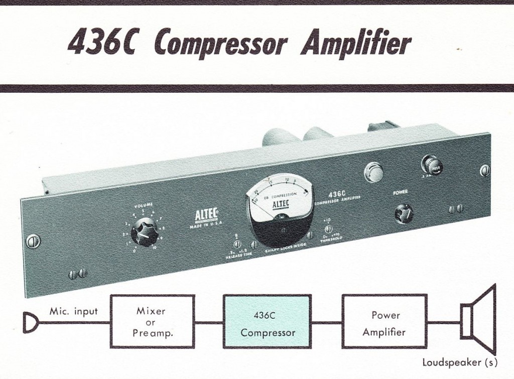
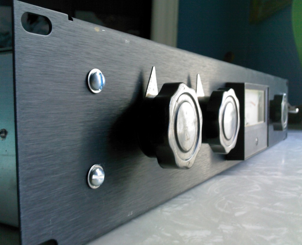
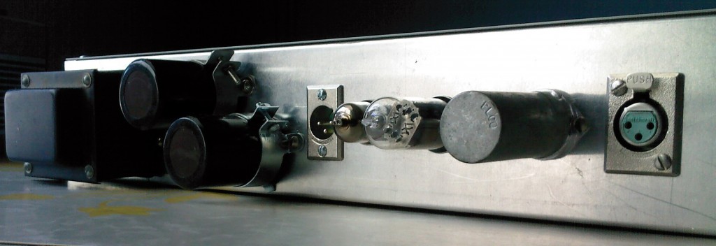
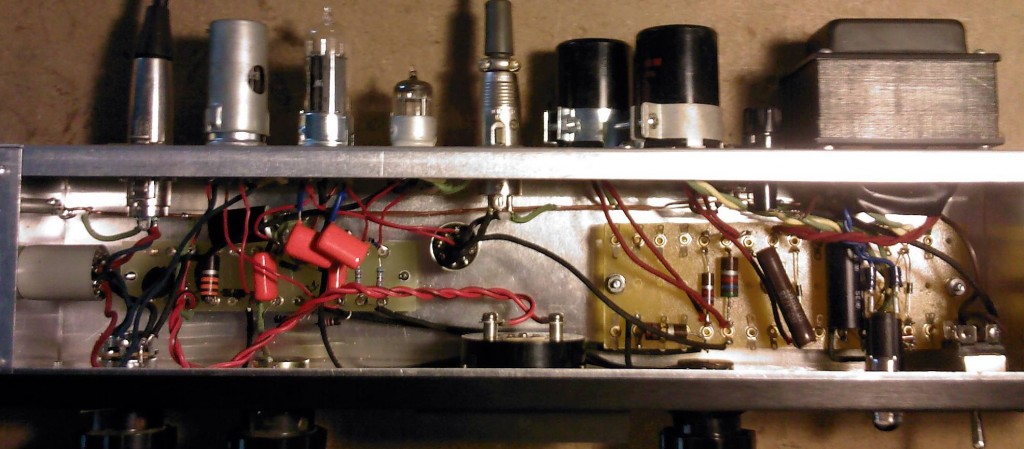
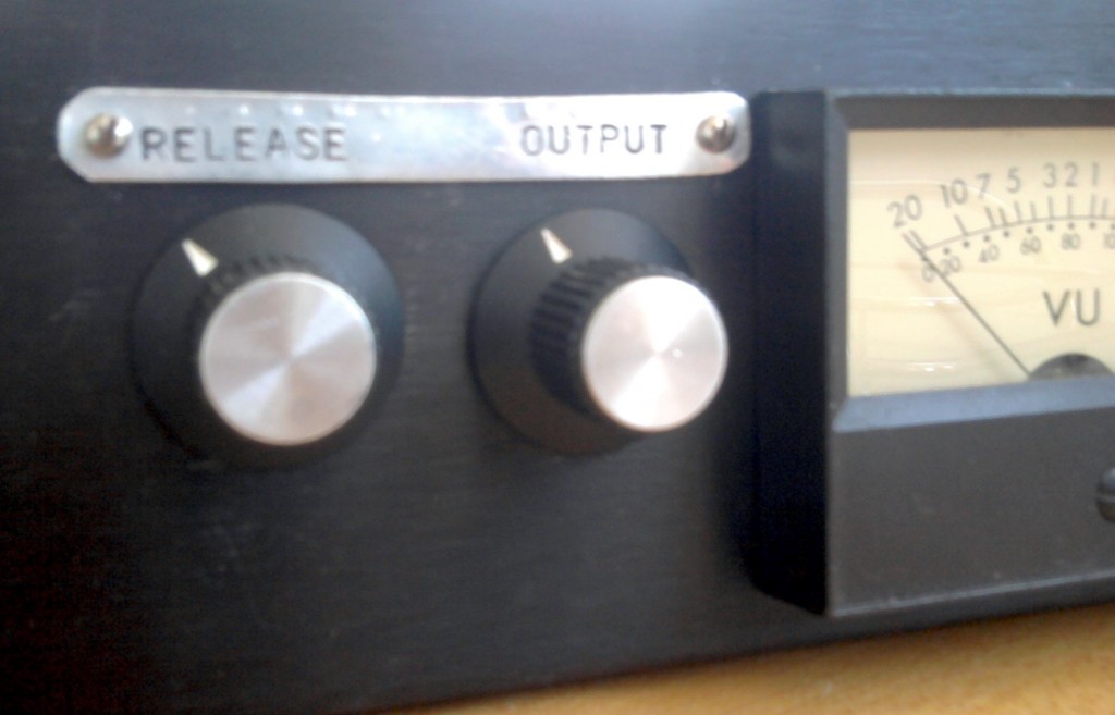
 In a previous post, we looked at the Altec 436 vari-mu tube compressor. I built one of these a few years ago, and it never really got used all that much because the output level is so hot. The 436 is a very primitive compressor design, and it sounds awesome- but it was also built primarily for service is installed sound systems: industrial paging use, etc. The stock 436 circuit adds a lot of level to your signal if you have the input level set high enough to actually cause significant compression. I built an external attenuator box using a 600-ohm Daven T-pad attenuator and a UTC transformer to re-balance the signal, but this was not really an ideal solution. The box was pretty big and heavy and I generally could not be bothered with taking it out and setting it up.
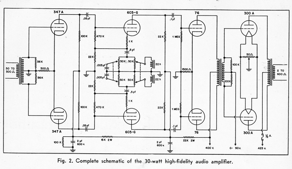
 The solution came to me when I was examining the circuit of the Gates sta-level. Here’s the schematic if you want to take a look. Now, this may look a lot different than the Altec 436 schematic, but the differences are not too significant – other than the fact that the gates has a regulated power supply, the circuits function in the same way; the main difference is the particular types of tubes that are used. Both are fully-balanced vari-mu compressors which are staged as (input transfo)-(attenuator pot)-(vari mu input amp)-(driver stage in Gates only)-(output amp)-(output signal rectified, timed, and sent to grid of input stage to regulate input stage amplification)- (output transfo).
The Sta-level, however, has an output level control, whereas the Altc 436 does not. So how do they implement this?
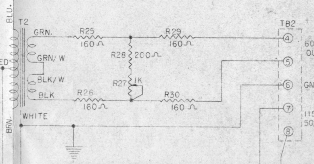 Pretty simply. 5 resistors and a normal linear taper pot give us an output loss that we can vary between 10 and 16db, while still maintaining a safe operating impedance. In all fairness: the BEST way to do this would be to use a balanced H-pad variable attenuator, which would give us the ability to vary the output from NO loss to, say 20db or so; but balanced H-attenuators are crazy expensive and very large physically; too large to fit inside an altec 436 chassis, certainly. Another option would be to use a variable T-pad after the output transformer, and then add an additional 600/600 transformer after the T-pad in order to re-balance the signal (there is a certain vintage vari-mu compressor that works this way, but i can’t seem to recall which; anyone?). This solution is also not ideal from a cost and size perspective, although it would certainly be less expensive than the balanced H attenuator.
Anyhow, the major downsides to the ‘Gates-solution’ are: 10db loss is inevitable; output impedance will vary slightly with use of control; variation range is limited to 6 db span. Well; i used my output modded 436 in a session yesterday, and for what its worth, here’s what I can tell you: the minimum 10db loss is welcome – it put the 436 into the same basic operating range as my 1176 and Distressor; the impedance mismatch (into a Lynx Aurora) did not cause any audible problems that i could detect when used on guitars and drum machines; and the 6db control range was fine as well – i was dialing in levels and getting sounds into Pro Tools with no fuss.
****
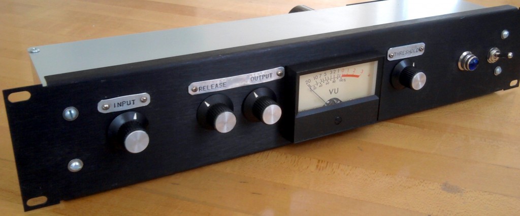
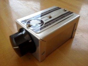
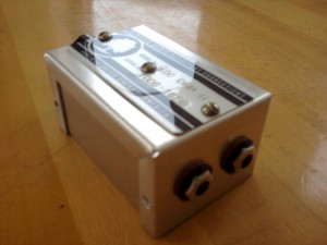
Before I drilled a fresh hole into the face of my 436 clone, I built the intended circuit into a tiny outboard box. When the design confirmed itself, I added the circuit into the 436 itself. But about this little test-circuit box: it’s lightweight enough that it can simply hang off the patchbay, supported by the patch cables themselves. Now every vintage mic preamp that I have can be given variable output control quickly and easily. This will allow me to dial in extra-gritty sounds using the preamp gain control (which is generally interstage rather than input or output), and then use this little device to get the level back down to an appropriate level to hit the convertor.
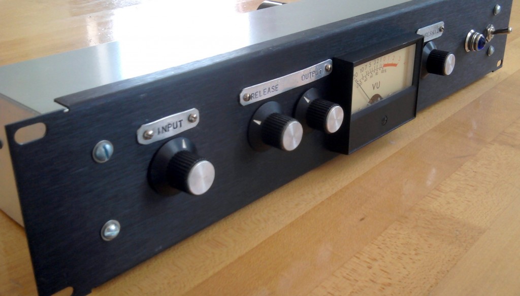 If you own a vintage Altec 436 or 438 and you find that you have to battle the high output level, I highly suggest that you give this modification a shot. It’s very easy to simply build it into an outboard project box at first in order to see how you like it before you drill a hole in yr Altec. And if you use any vintage tube gear in the studio: try making one of the little boxed-versions of the circuit. It will really open up some new creative and sonic possibilities for the gear you already have.
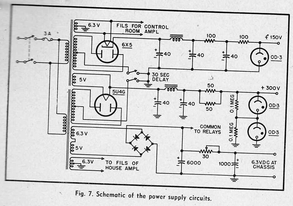
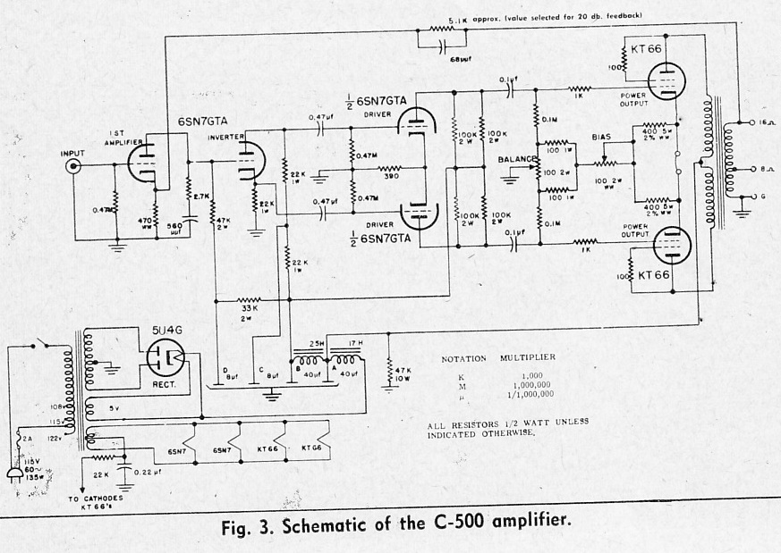
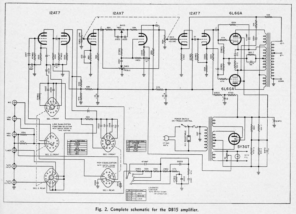
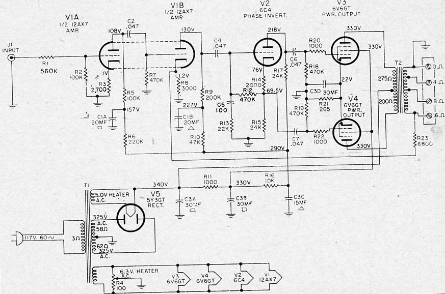
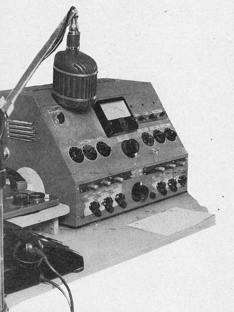 Some more interesting bits from AUDIO magazine c 1955: plans and schematics for a radio station mixing console. Very little in terms of equalization devices, and no compressors discussed, but a wealth of ideas for low-level and line-line level amplifiers and mixing circuits. Download the entire piece as a 4-page PDF:
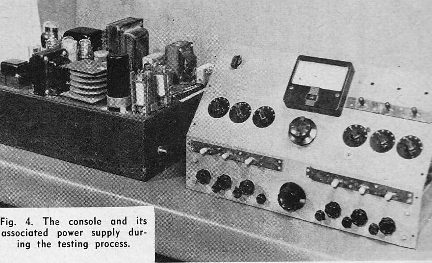 There is little of real interest here in terms of a complete system, as the system discussed is a mono mixer; but if you are interested in some simple, novel mic preamp and line driver plans, you might find this worthwhile. Personally I am drawn to the OD-3 regulator tubes; i know zero about voltage regulation tubes; I have always used Zener diodes in the past when i needed regulated voltage; but the very simple way that these tubes are used here leads me to believe that they are pretty easy to work with.. Might wanna try them out. They are just $5.15 at AES.