For my non-technical readers: a phono preamp is a device which does two basic things: 1) it equalizes the program that the phono cartridge picks up off the LP record, basically by boosting the low-end and cutting the high end, with this action centered at the fixed frequency of 1K hz (for full details on the ‘RIAA compensation curve’, and why it is necessary in the manufacture of LP records, read here); 2) secondly, a phono preamp must amplify the signal of the phono cartridge to roughly line-level (IE., the level that would come out of a CD player or VCR) and also deliver this signal at a low enough impedance such that it can be in-put to any receiver or consumer amplifier that it might encounter. Here is my attempt at a self-contained version of the phono pre-amp section from the Marantz 7 hi-fi preamlifier.
(web source)
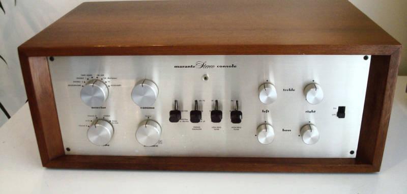
I’ve never heard an actual Marantz 7c in action. Considering that this dude, who does not seem like a total flake (based on his sales record) is selling one for $4,999 on eBay, I had to assume that it sounds fine (at least). Marantz is one of the legendary American Hi-Fi brands from the ‘Golden age of Hi-fi,’; their original line-up of products (before Saul Marantz sold the company) are widely lauded for both their sonic and aesthetic traits (see here for previous Marantz coverage on PS dot com).
(web source)
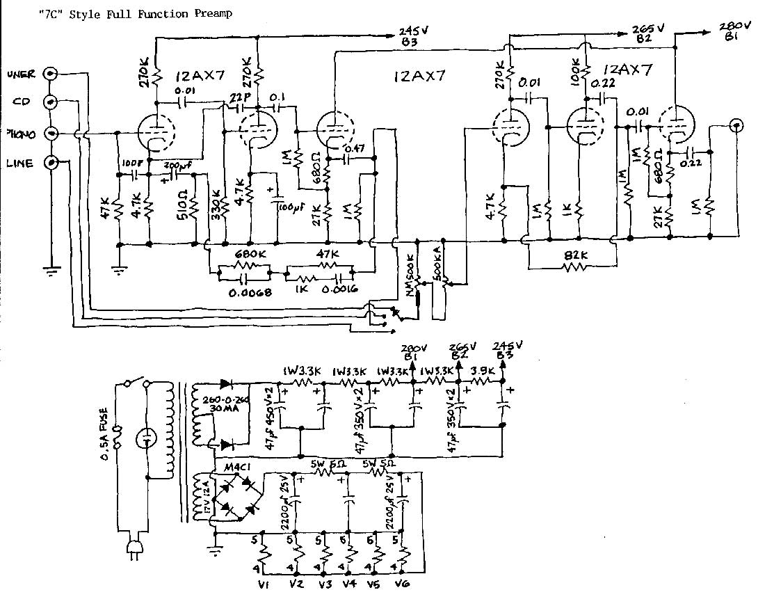
Above, the schematic that I used for this build. It is a simplified version of the Marantz 7C, omitting such features as pre-RIAA disc compensation curves and bass/treble controls (for the complete 7C schematic, see here). The only change that I made to the audio section is that I added a 1K resistor between the signal output (the .47 cap) and the output jack. Couldn’t hurt, right? The phono pre-amp section consists of the three triode stages that you see at the left. The three stages to the right are additional make-up gain that follow the overall balance and volume controls. Important to note: the output of the phono stage is a cathode follower. This means that the signal is derived from the cathode of the tube rather than the plate. This results in very little voltage gain (in that particular stage) but… also… pretty low impedance. Which is what I wanted.
Above, the RCA RIAA phono preamp as published in several of their “Receiving Tube Manuals.” I have built this RCA circuit before; while excellent-sounding, it does require an additional stage of amplification (I used a cathode follower circuit) to lower the output impedance of the device if you want to be sure it will ‘play-nice’ with all yr other kit.. Notice the note at the output leg of the circuit: “220000 ohms minimum.” Wow! That is very high impedance. The only devices that this thing should feed are either the grid of another tube or possible a FET. This condition makes the RCA circuit (on its own) insufficient as a stand-alone device. And RCA did not really intend this to BE a stnd alone device; rather, they intended that you would build this into an amplifier where the circuit could directly feed the input grid of a preamp tube. The Marantz 7c circuit, with it’s third cathode-follower stage, does not have this limitation.
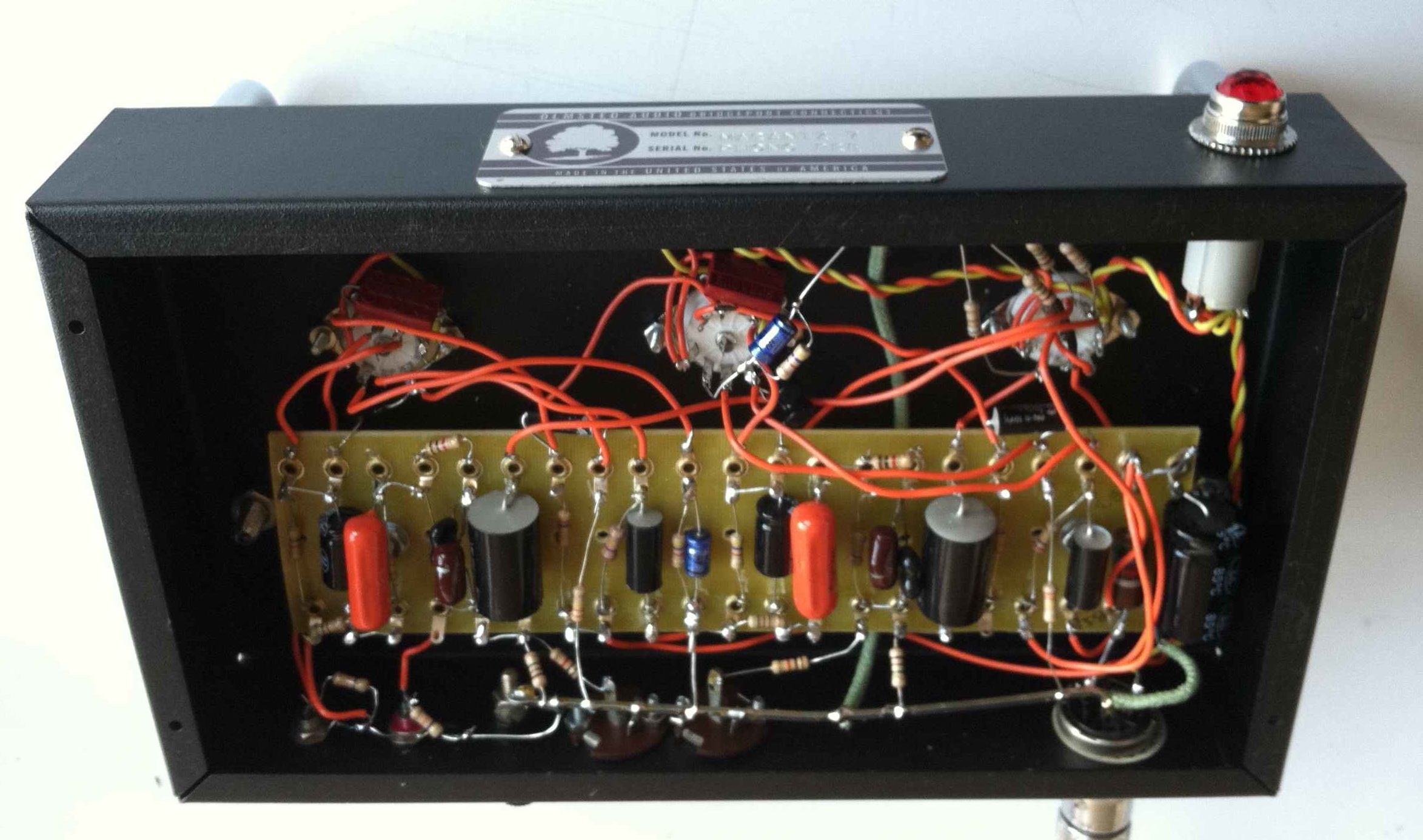
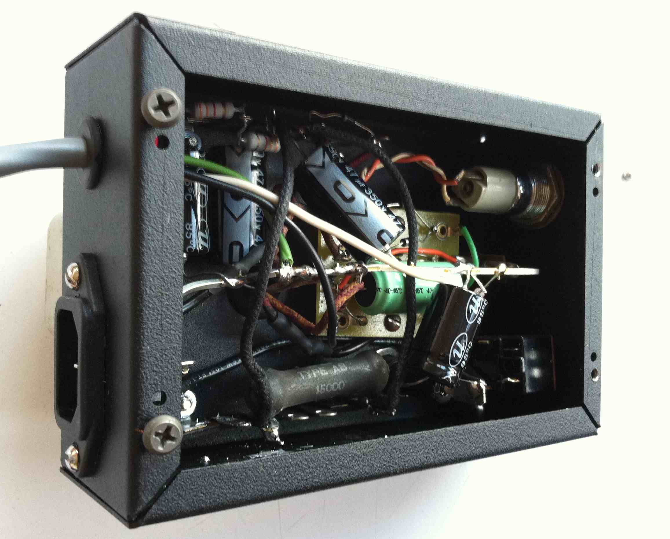
Above, the interior of the completed piece (audio chassis). Note the French SOLEN coupling caps (my favorite due to good performance, reliability, and small size) and single ground buss (the piece of copper that runs along the lower edge). RCA used the single ground buss technique in most of their broadcast equipment, and AFAIK, this grounding style cannot be beat for performance and ease of manufacture.
Above, the interior of the power supply. I built the unit into two seperate chassis: audio and power supply: this was an aesthetic preference of the customer, and it also makes good sense when you are dealing with the miniscule audio voltage that emanate from a phono cartridge. Sure enough, the finished piece exhibits no (z-e-r-o) hum whatsoever. I did not follow the Marantz 7C schematic for the power supply; I just built what I though was neccessary: a DC supply for the filaments and a B+ chain with 4 stages of filtering (no choke). I used an NOS RCA power transformer that was a lil’ bit too exuberant for the 280V B+ requirement, hence the large-ish 15k ohm resistor near the bottom (the Marantz 7c schematic called for a 3.9k ohm in this position). When all was said and done, after experimenting with a three different resistors in this position, I was within 1% of the voltages specified in the schematic.
So how does it sound? Very good. Compared to the RCA phono pre, it rejects WAY more RF; it is very rich, extremely quiet, and the low-end response is so, so much better than the phono pre amps that come built into modern stereo receivers. I QC’d the piece with a good cartridge and a clean pressing of TUSK and it was “as Lindsey Buckingham intended it to be heard.” If you are thinking about making a tube phono preamp, give this one a try; build cost is very low and it went together very fast with no hassle.
View Comments
The whole point of the Marantz 7 is its (quite good) tone controls, not so much its phono stage. There are much better phono stages, but you have to look at them as part of a system with the cartridge they are going to work with.
Hi Brad,
I find I must disagree with you about the phono stage in the Marantz 7c.
I am a paid musician, as a second livelihood.
The first time I heard a Marantz 7 phono stage I was 16 years old, and it really caught my attention.
About 4 years ago I got lucky and snagged a 7c, 8b and 10b for a great price from the widow of a friend who owned the equipment.
Yes, the tone controls are very good, but I find the phono stage to be toe tapping, goose bump making good! I find it to be fast and warm, images very well and is just very musical.
I have had probably 30 musicians/friends come over and listen to it. They have all left shaking their heads in disbelief of how much great sound can be taken from a record groove. I had several in tears.
I have listened to Southerland, Lehman, McIntosh, Pioneer Spec series, Dynaco Pat 5 Bifet, fisher, and Hafler. My Marantz 7c eats their lunch with the stock bumble bee caps in it.
System-
VPI Traveler table w/ Denon DL160
Thorens TD125 MkII with Shure V15 Type III/Grado GCE 1+ carts
Marantz 7c pre
Marantz 8B with Russian K-40Y coupling caps and Mullard EL34 XF2
1980 Klipsch LaScala speakers (Alnico magnets)
Luminous Audio Synchestra Reference speaker cables- Pure Ono cast copper.
Thank you, Bruce
I agree, By coincidence run into a clone and still are amazed by it's real live sound.
Nice! Very interesting. I was wondering in reference to the input possible issues using differente magnetic cartridges like MM, MC etc. Should be needed some kind of input load section selection or even a little transformer for good signal level?
A transformer is needed and desireable ONLY with low ourput, low impedance moving coil cartridges. Most others are designed to work into 47 k impedance.
Yes, actually is usual to find a basic R-C configuration with a 47K resistor. I built this ckt and got some interesting oscillations. Guess it is a problem of the feedback network. I hope to find the time to fix it up and try it.
The auction sites are awash with boards-empty or stuffed-for the Marantz 7 preamp circuit. The bare boards are ten to thirty dollars, the stuffed ones without tubes maybe $100. Just provide a box, a couple of volume pots or step attens, and power supply and you are in business.
The exact same board is listed as a McIntosh C22 kit also since the Marantz 7 and Mc C22 are in fact electrically nearly identical. Who'd'a thunk it?
Hi Chris,
I have build this phono too and found your blog very helpful. I did some minor changes to the riaa network and made a loosely regulated psu. I have now started a thread on diyaudio because of some strange oscillation occuring. Maybe you can help. You seem to have build more than one of them. I have tried "everything" and couldnt get it running properly. I really dont want to give up, because I could listen to this preamp and liked it a lot.
Cheers, Merten
Hi Merten. If you made ANY changes to the RIAA network, which is part of a FEEDBACK network, you are certainly inviting oscillation problems. If I were you, the first thing I would do is to wire the RIAA network EXACTLY the way that it is is in the schem and see what happens. You also suggested that you changed the PS design. Remember that no more than two (2) stages can be fed from the same B+ filter point. If you have all three stages fed without R/C isolation you will get feedback.
Thank you, Chris, for your reply. I already tried/examined all the things you suggested. No luck. As long as I can find possible causes for this I will keep trying. At the moment all is very mysterious.
Hi Chris, it works! I tried again, what you suggested. I used the more or less original values for the RIAA network and changed the little feedback cap from 10 pF back to 20 pF (which I had'nt done before). It sounds like I remember it. Great, very good timing, nice tone. A very good flow. Thank you very much!
The type of power supply layout used in most all classic tube gear is called a graded power supply. The power supply starts at the end of the signal chain and goes to the first with a resistor or inductor (choke) in series and a capacitor to ground. This is on the principle that the earliest stage has the smallest signal and therefore needs the least voltage to swing. Look at any guitar amp design, or any old radio schematic.
Any alternative layout needs a good deal of experience and usually careful testing to pull off. It's also worth commenting that parasitic oscillations that operate above the audible sound range cause a great deal of trouble that even somewhat experienced people can have trouble with. Those who refuse to obtain and learn to use a scope are responsible for a lot of unnecessary problems.
How much? w/o tubes.
Juan,
email me at chris (at) preservationsound dot com
c.
Chris, have you run tests on this preamp to determine if it's the same RIAA adherence and distortion specs at Marantz? As I recall, Marantz was quite accurate to the RIAA curve for those days, and Sid Smith would weak individual components to make each preamp measure the same.
The Marantz 7 is a good phono preamp circuit from that era. I'm not convinced that it runs quietly enough to bring out every thing that a top-drawer 2013 cartridge can produce, nor can it handle cleanly the dynamics on some records, but it was very good for the tube era. More on the clean and accurate side of things than the "warm and fuzzy" side.
-- Tom Fine
Hi tom. No, i never did run a sweep on any of these phono pres, cos i
Used the exact right value parts and they sounded great so i didnt take the time.
Ur right, tho, next time i build one i should sweep and chart it like i do
With the mic preamps. C.
Hi Chris,
This seems absolutely delightful. I'm in the middle of building a phono preamp/mixer for use in a Telefunken Opus Royal console I recently acquired. The turntable was replaced with a nice Garrard, and much to my disrespect, a Radio Shack solid state preamp which also resides within the cabinet. Since the TFK is mono, and the turntable is stereo, it loses the left channel due to the ghastly Y cable that "sums" the two channels.
I'm looking to destroy these two birds with one vacuum tubed stone. I'd like to know if you could make available the power supply schematic that you used for this CKT? Very much looking forward to trying this preamp! Thanks, Chris.
Much respect,
ChrisK
Hi chris. I dont have a schematic per se; its really utterly
Conventional; the b+ is four stage r/c with 80uf for the first
And 40uf for the next three. The heater circuit is similar to the marshall studio 12 gtr amp heater circuit.
Good enough to go on. Thanks Chris!
Can't find where Marshall ever made a Studio 12 amp. There was a Studio 15 with DC heaters on the front end but pretty conventional DC filament circuit and certainly not floating high above ground. Care to elaborate?
could be a typo. i wrote this ages ago, i can't remember. i've built that DC filament circuit 100s of times and it works fine, thats all i can tell ya...