Note: I performed extensive frequency, level, and actual studio tests on the 864 clone today, and several interesting details were revealed. Text has been edited to reflect that.
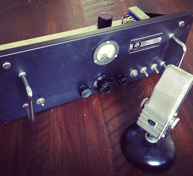
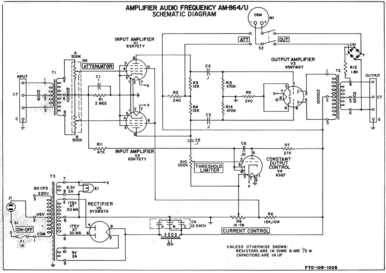
From 1954 through at least 1963, the Federal Television Corporation built an audio limiter called the AM 864/u for the US Air Force and US Army. The 864 is a simple, rugged device that accepts 600 ohm balanced or unbalanced line-level signal, offers a single front-panel input-attenuator control, and compresses the output level at a 10-to-1 ratio once the threshold point is reached. The output is also 600-ohm balanced or unbalanced, and it offers a maximum 36db of gain. The rear panel of the unit displayed the threshold and ratio controls, although these are confusingly referred to as (respectively) CURRENT and THRESHOLD in the manual and schematic. Attack and release times are fixed, and the manual indicates them at .05″ and 2″ respectively.
Download the original 1963 manual for the AM864 (apologies to whomever did the epic work of scanning this 55pp document; I have long forgotten where I got this file from)
DOWNLOAD: Federal-AM-864-U-Manual copy
This is going to be a very long + detailed +technical article, so I’m going to ask y’all to please click the link below if you dare to READ-ON,,,,
After 16 hours of fabrication and assembly, my Federal AM846 clone was finished, and I am really impressed with the sound. Far more than I ever have been with my Altec 436 (or any original 436/8 that I have ever heard, either….). Now, there are about a million threads and article on the internet written by other dudes who have scratch-built these things, so there is no need for me to offer a full account of the proceedings. If you wanna try building one yrself, I suggest you start where I did: google “Federal AM864” and start reading+ downloading. However: as is often the case, I made many slight modifications to the unit that you might find helpful. So consider this article as yet another addendum to the already-substantial body of online information regarding this circuit.
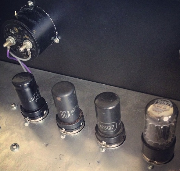
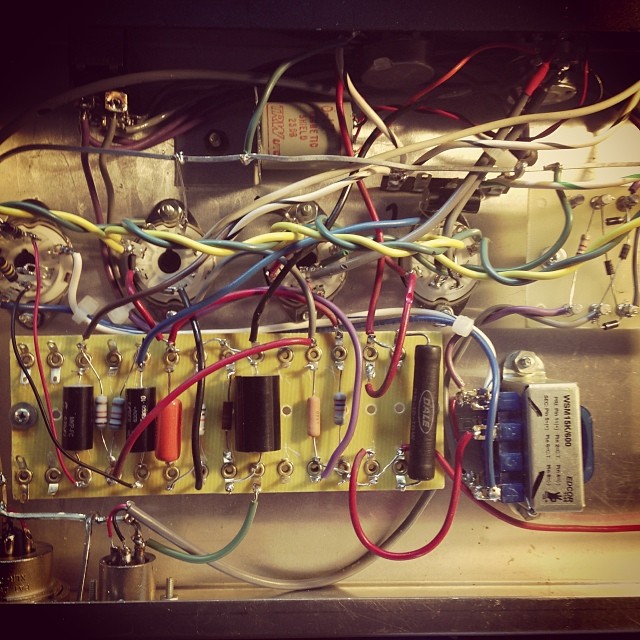
For the resistors, I used 2-watt metal oxide power resistors for anything that dropped a lot of voltage, and carbon-comp or carbon film for the rest. The BIG resistor at the right is a Dale 15k 10w wirewound. I have no idea why the schematic specs a 10w resistor here – seems WAY overkill – but again, anytime you are going to drop a lot of voltage, use a wirewound or metal oxide resistor. IMO, Carbon comps are just too noisy for this application in pro audio gear (but – they are FINE in guitar amps, where the overall system noise floor is necessarily much higher owing to inherent pickup noise ETC).
I naturally moved the ‘Current’ and ‘Threshold’ pots to the front panel as well. One note regarding the pots: the schem does not spec audio or linear taper. Now, the input atten pot obvs needs to be audio taper. The other two pots would seem to want to be linear taper. I used a 500k linear for the ‘threshold'(aka ratio) pot, but I was all out of 1/2watt 1K linear pots, so I used an audio taper here; it works, but not very well – all the action happens at one end of the swing. Gotta change that out.
The release time of the 864 is very slow, and I wanted to speed it up – it’s pretty rare that I want a 2″ release time in the studio. The release timing is apparently dictated by C1 and R1. I tried changing C1 to a .1, a .2, and a .5, but they all caused some degree of motorboating weirdness. So i changed R1 instead – to 1M- and this shortened the release time considerable with no ill effect.
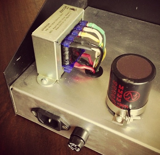
Since the Edcor does not have a 5V winding, and there was not enough current available from the filament winding to use a 6×5 (6-volt) rectifier tube, I just used a pair of $0.02 IN4007 diodes instead. If you do this: remember: rectifier tubes allow for a gradual build-up of B+ voltage in a circuit. So if you chose to use a solid-state rectifier (EG., a pair of diodes), it’s important that you incorporate a standby switch in the circuit. Otherwise everytime you power the thing on, the tube plates will get hit with full B+ voltage when they are still cold. This will adversely affect tube life. In this case, I implemented a standby switch in the standard manner: it acts to switch the 350v center-tap to ground.
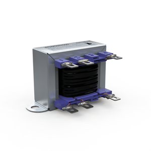
To the right of the Edcor you can see the filter cap can. This is my favorite guitar-amp muti cap, the JJ 500v 20/20/20/40uf. They sell for a not-cheap $17 with mounting clamp, but I have bought dozens if not hundreds of these things and they are a great price/quality/size value.
If you look at the original schem, you will see that the B+ filtering consists of simply two stages: 12uf, followed by a 15h choke, followed by 24uf (achieved by paralleling two 12uf sections). Now, I may be a simple cave man who fell into some ice and later got un-thawed by your scientists, but just two stages of power-supply filtering in any audio device seems like a terrible idea (even in a fully differential device where any common ripple should in principle be cancelled out in the output transformer). Clean that shit up man! Jesus. So i omitted the choke, paralleled two of the 20uf sections of the JJ, and ended up with a 20uf/40uf/40uf three-stage filter. I isolated the stages with 470 ohm 5-watt resistors; these resistor values gave me 191 volts on the 6SN7 plates, which is a mere 6v deviation from the reading spec’d in the manual. Done and done. Now, in general, I am in favor of chokes, but I was trying to keep the cost down on this thing, and I am satisfied that I ended up with a much cleaner power supply than the original unit had.
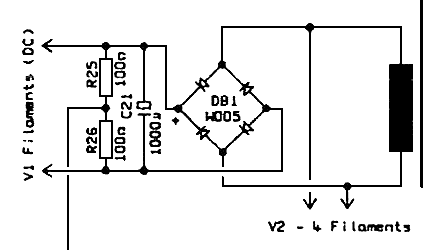
OK bored yet? The final power supply note: heater wiring. The original schem indicates a really janky heater wiring scheme in which one side of each heater (and one side of the transformer filament winding) simply go to ground. Now, who fkkn knows, MAYBE due to the fully balanced nature of this unit, this has no adverse effect in the end, but in 99.99% of cases this type of heater wiring scheme will make for a noisier unit. Since the Edcor power trans has a center tap for the heater wiring, I simply ran that to ground and then wired the heaters each with their own heater-secondary lead. This is the standard way that most AC heaters are wired in pro audio gear. Oh and a note on that: ordinarily, i would never build a pro audio unit with AC heaters; instead, I build a simple DC supply like this:
*it is magnetically shielded (otherwise it will pickup and amplify hum) – so no Edcors here!
*the high-impedance winding is truly center-tapped, with good balance.
*it has a wide-enough frequency response
*it can handle enough level (dbm) for line-level applications
*we understand that a secondary winding of less than 10K will give us less-than-spec’d total-system-gain, and a secondary winding of more than 10K will give us more-than-spec’d total-system gain. Practically speaking, and value between 5k and 30k should be fine.
Based on what I had in my transformer-case that day, I chose a UTC O-10. This is a 30K c/t: 600 ohm transformer intended for push-pull-plates to line application. Note that I have ‘flipped’ it and I am running it in reverse, but this has never been a problem with audio transformers in my experience. AFAIK, a 30K c/t : 600 is a 600: 30K c/t. The O-10 is full-frequency, but it is only rated for +8 operation. After extensive testing, I have found that it indeed gets distorted below 100hz at approx +10 level. Plus, its just got too much voltage gain. I am going to order a Sowter #8540 and try that out,,, stay tuned.
Nonetheless, chassis placement of unshielded chokes and audio-transformers is critical relative to power transformers, so use good practice and scope out your placement using the classic headphone technique. If you don’t know this technique, you can read about it any of the old military signal corp course books or just check it out at this link.
Now, full disclosure: I have always and only used these Edcor transformers single-ended, cathode-follower style. Never with DC current on the center tap. After running my 864 clone for a couple of hours in a mix session today, I did not notice any issues. But will it eventually melt? Only time will tell I suppose. I will probably just swap it out for a nice 10-watt Motorola that I pulled from a PP 6K6 broadcast line amp,,, stay tuned for that as well.
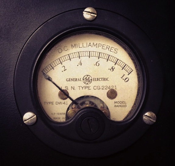
It works pretty well. It shows output level moving, it shows compression happening, no, it’s not set to any sort of objective scale but the needle hangs out in the expected area and it provides good visual feedback of what my ears are telling me. Testing shows that +15db correlates ‘.8’ on the scale. I did notice that the diode bridge introduces noticeable distortion in the output audio, as well as a slight loss of level, so I would not recommend actually using the meter for output level indication while tracking or mixing.
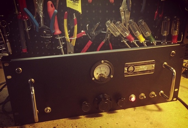
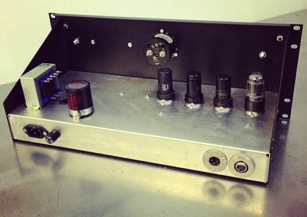
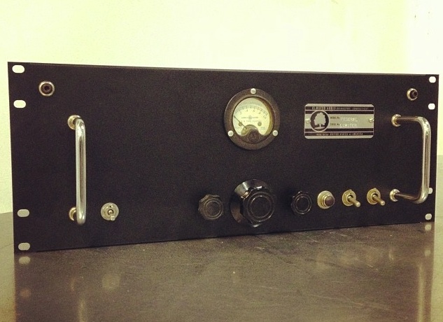
My final comments will concern the chassis fabrication. It was important to me that the thing look right; I mean, christ, it’s gonna live in a recording studio where clients have reasonably high expectations about the quality of the kit. I don’t think that you can buy a complete chassis these days that in any way resembles the original AM864 chassis, but we can get to a pretty reasonable approximation by making a system from various sundry components. In my case, I used an old Hammond 1444-series 17x8x2 aluminum box that I had in inventory (no longer made – try this instead). I made the bottom plate out of aluminum sheet that I keep around, and the faceplate is a $15 Mid-Atlantic flanged-aluminum four-space blank panel that I picked up at RedCo. The steel side brackets are some ancient dead-stock Bud units that are long out-of-manufacture, but Bud now offers these instead, which should perform a similar task. The handles on the front of the unit are my favorite Bud H-9160b 3.5″ chrome handles. Put it all together and you get something like this:
Now, the 4-space panel turned out to be excessive – I could have gotten away with a 3-space – but until I knew exactly which meter I was going to used, I could not be sure. In the future, I’m going to use the 2″ high chassis, a 2″ round meter, and a 3-space panel.
Further reading:
Here’s a dude who manufactures a Federal AM864-inspired unit for $1499 street
Here’s a nice-looking DIY build of this unit from GroupDIY
MASCO was one of America's leading manufacturers of public-address equipment during the vacuum-tube era. The…
Audio Devices, INC manufactured the popular 'Audiotape'-brand 1/4" tape in the 1950s and 1960s. They…
Starting this month I am scaling back the monthly WPKN FM radio show to one…
Im back from 2 weeks in Japan, time that I primarily spent hunting for records.…
Available now on LoveAllDay Records : the new LP "Secular Music Group Volume 1"- avail on vinyl…
This month's Preservation Sound Radio program will air tonight Tuesday May 21 at 8:30 PM.…
View Comments
observe polarity of windings in Edcor ; it can't be used as PP OPT , unless you are able to manipulate with CT and re-wire it
Hi there. Thanks for writing in. Are you certain that this edcor cannot work as a push pull output trans? Because it seems to be working fine. Can you please explain?
in every PP OPT primary windings are connected in antiphase , that being only way to achieve core DC flux cancellation ;
however - ignore my comments
I'm having brainfart these days ;)
Chris, this build looks great. I am right in the middle of putting one together and was curious how you handled the center tap of the output transformer. It looks like you just left it, but I can't tell for sure. I wonder about it, just not sure if it wants to reference ground or not. Haven't built anything with a balanced output transformer.
Hi there pasquale. I did not ground the C/T of the O/Trans, and I don't think it would be necessary in most cases. Generally we just let them float relative to ground. I can't remember all the old 'best grounding practices' papers from the AES journals, but i think that ref'ing the trans secondary to ground is more likely to cause hum than anything else... although in many instances it will simply be benign but unnecessary. c.
Did you try the Sowter 8540 transformer?
Not yet. But I plan to. c.
Hey Chris nice build!
I was planning on adding D/C filaments to my pre amp project and I saw your schematic above.
With a 6.3v supply, using a bridge rectifier would give me 7.62v D/C. My 12ax7 tube data sheet suggests using 6.6 or 13.2 max so how do you get round that problem? Are you feeding your tubes 7.62v? does it hurt 'em?
Great work anyways!
John.
Hi john. The diode config that i use creates some addl voltage drop. The filament voltage ends up being 7v. It has never caused a problem with these low current voltage tubes. C.
Hey Chris (or anyone else out there who knows!),
My filament supply keeps burning out 2 diodes on the bridge rectifier when I power my unit up. I'm using a 2.5 amp 6.3vac CT Hammond tranny. The rectifier consists of 4007 diodes.
Are you able to run the filament supply without the tubes plugged in? i.e. Zero load? I was testing voltages before finishing the unit and all other measurements seem perfect.
Anyone who can advise would make my day!
Cheers,
John
Hi John. I have always used this circuit for DC filaments:
http://www.dreamtone.org/images/Studio%2015%204001%20year1988.gif
I have built it literally dozens of times and it has never let me down. Never lost one diode.
A few ideas:
Keep in mind that the 4007 can only tolerate 1 amp; your transfo can put out more. So there may be some short in your circuit that is causing the diode to fail before the tranfo fails - essentially, the diode has become a fuse for the transfo secondary.
Another thought: maybe you simplu miswired it? I know for a fact it works and its reliable. I've never had a single unit come back to me.
c.
Hmmmm my bridge rectifier is sharing my B+ ground... Could that be the problem?
Cured now. Thanks Chris for the schemmy
Chris ... the link is broken ... can you share your DC filaments schmatics ?
done
no image ... ooopsss! need your help again chris !
CT of your filament transfo needs to go to circuit ground. Otherwise, follow the schem that i linked to in my prior comment. good luck! c.
Chris, I have built this unit but my "threshold" pot doesn't do much. I'm curious what you did with pin 1 of the 6sq7. Looks like it should go to ground, but on the original schematic they reference their heaters to it. Anyway keep up the good work.