 The Craftsmen C-500 power amplifier
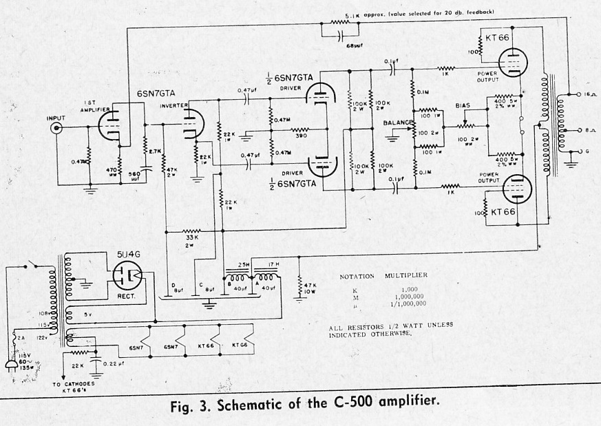
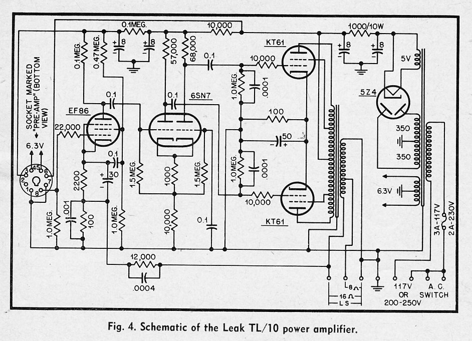
Today we have some hi-fi amplifiers from the mid 1950s to look at. Many of them use unusual output transformers with split primaries, so I am really not sure if it’s even possible to build these designs today. The Craftsmen C-500 pictured above uses a standard PP-VC output transformer; it also uses readily available, robust 6SN7 and Kt66 (aka 6L6) tubes. Check out the circuit in the output cathode bias; even though this is a cathode-biased amp, there is a provision for adjusting the overall bias, as well as a balance adjustment ( to allow the use of unmatched power tubes). Here’s a few more…
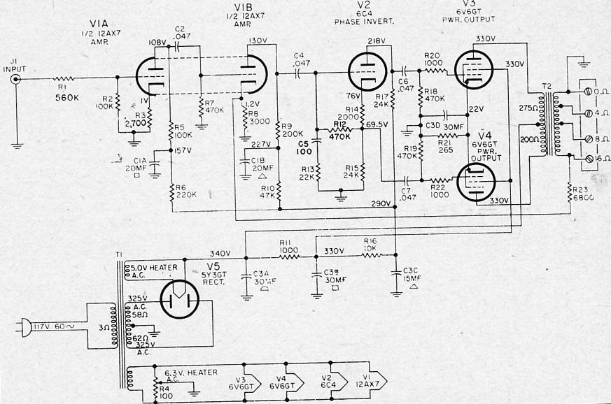 General Electric A1-300 power amp. This is a good simple design that will provide 12 watts.
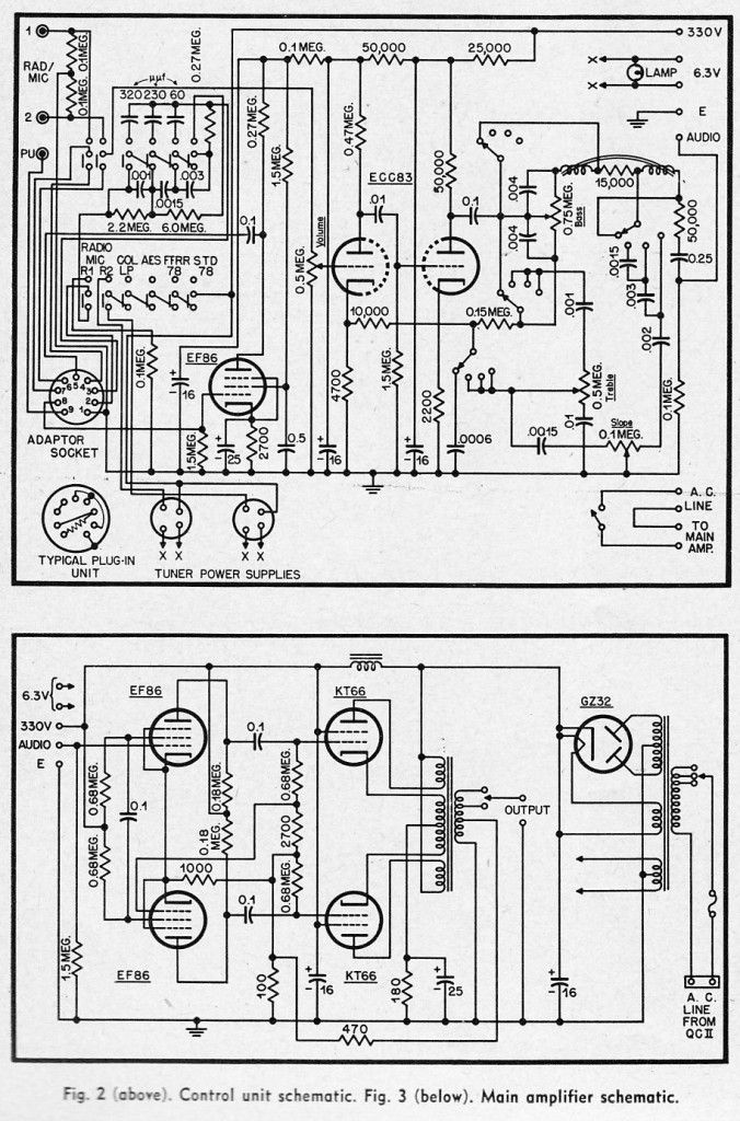 The Quad II pre-amp and power amp.
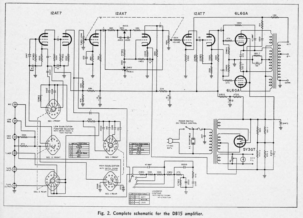
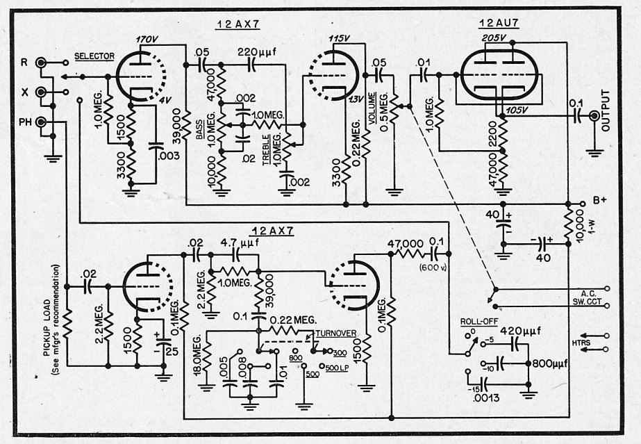 A DIY hi fi preamp design from 1954. Note the very sturdy parallel-cathode-follower output (the 12AU7 section). This could probably drive a 10K load pretty easily.
13 replies on “Hi Fi Amplifier Schematics c. 1954”
Most of these designs use cathode bias, which is not really good engineering in a high fidelity amplifier, now that we have convenient solid state rectifiers. Fixed bias with easily adjustable, stable bias adjustment is the only way to fly.
One of the most useful books to get is David Manley’s VTL Book. The early VTL products are all cookbook stuff, but David knew WHICH cookbooks to use, which is a secret all chefs know. The VTL bias circuit is exactly what any guitar amp maker with common sense does, too: a small resistor in the cathode circuit acts as a current shunt and a fuse too if the tube shorts. You put the bias supply on a little board with pots and test points from the cathode end of that resistor next to each pot. Oh yeah, you put the wiper in circuit so if it goes open the bias voltage goes HIGH instead of to ground. The resistor is of low enough wattage that if the supply fails they fail before the opt primary does.
Look at the McIntosh MA230 carefully. It shows the right way to do the cathode-and-plate-windings thing, which you also see in some Fishers, the original Quad, and lessee, that Bogen there.
I found this ad awhile ago-it’s for a now finished eBay auction-and whoever the seller is, I think he knows his stuff. I put it on Usenet:
<<These are one pair of Output Transformers for the McIntosh MA230
amplifier. These were bought NEW by me directly from McIntosh in
Binghamton in or around 2009 for a project I had planned but never
started. They were the last pair that McIntosh had in stock, from a
run by the original vendor (either Endicott Coil, Endicott NY next to
Binghamton or Magnetic Windings, Easton PA, who made the Marantz 8B
and 9 transformers for VAC when they did the reissues) done sometime
in the late 1980s.
One is in the original sealed box as shipped by McIntosh Binghamton.
The other has been opened for inspection and will be repacked and
resealed.
A pivotal role in the resurgence of DIY tube amp building was played
by the MA230 output transformer when Bruce Rozenblit of Transcendent
Sound found a supply of these and designed a project using these,
which he wrote up in Glass Audio magazine, "Build 70 Watts of McIntosh
Power". The project became such a success the original supply of
transformers was exhausted and McIntosh authorized the original vendor
to supply a third party-I think it was Audio Classics in Vestal-with
another run of these (at least 100 pieces) and Mc themselves bought a
few for replacement stock as interest in the 230 had greatly
increased, plus calls from DIYers. I bought the last two for a
project, which I have decided not to pursue.
Bruce's amp ran a pair of 6550 or KT88 tubes at a pretty high B+ (in
the fashion of VTL which was the in vogue high end amp at the time)
for about 70 watts midband, with 20 Hz response somewhat down from
there. Later, Richard (RiMo) Modafferi designed an EL34 amp he wrote
up in Glass Audiio as well which was much more conservatively
designed, using as I recall EL34 tubes.
The original MA230 was rated at 30 wpc but these transformers were
severely overdesigned for that. Between 40 and 50 watts is probably
the best realistic rating for them.
These are NOT the McIntosh "Unity Coupled" multifilar primary
transformers used in the MC-30 through MC75 amplifiers, which were
wound in house on C-cores. They are conventional transformers except
they have a cathode winding similar to the Quad II. Because of the
feedback these provide, the driver circuitry has to provide a fair
amount of drive to the control grids of the output tubes. These are
NOT an upgrade for Dynacos! You can copy the MA230 circuit, use
Bruce's or Richard Modafferi's circuit from Glass Audio, or design
your own.
Many listeners who like HIGH FIDELITY and not the signal modification
of SETs and such have claimed the MA230 when operated as a straight
power amp is the best sounding amplifier Binghamton ever put out. I
have heard Bruce's project amp and a version of the RiMo design (with
some minor changes) and both were amongst the finest tube amps I have
ever heard. The tubes run conservatively-the original MA230 used the
7591, a tube I dislike personally, but even so tube life is generally
superb as compared to other conventional amps. (The Mc class B Unity
Coupled amp will get the longest life of any tube amp from tubes but
the sonics are a matter of taste with some listeners.)
These may be the best output transformers in the world you can buy
new in box. Here's why: They were made by the original vendor (Brian
the parts guy didn't know but ex-Mc employees have told me it had to
be MW or Endicott) at a time when they still had (many or most of)
the original female wind operators as when these were high volume
parts, the original fixturing, but modern wire insulation and
adhesives.
I am a former transformer/coil plant test technician and will explain
something no one talks about. In any transformer plant all the winders
(on electronics size parts, i.e., not power pole transformers and
bigger) are women. WINDING TRANSFORMERS IS WOMEN"S WORK and I do not
mean this as a pejorative: they deal with the fine motor skills needed
for fine wire handling and the repetitive nature of production winding
much better than the men do. The men get bored and goof off and either
quit or get fired.
As with vacuum tube manufacture, the highest quality transformers are
made in large quantity by staff who do a lot of them and whose work is
under constant QA analysis. Calibrated test equipment and a rigorous
program involving testing and occasional teardowns of assemblies and
feedback to the operator as to where she went wrong is feasible only
in such an environment. Don't be fooled by boutique vendors that
consist of one or two guys with a bunch of wind sheets they pulled out
of dumpstars and a worn out Universal winding machine who are winding
them in the rumpus room full of cat hair and potato chips when they
get an order or two. They CAN NOT consistently achive a uniform
product, and they don't. Insist on transformers made by professionals
in a business environment with cross-checking by multiple people who
do it all day. <<
The poster points out that Magnetic Windings of Easton, PA wound the original Marantz 8B output transformers. That isn't quite right. The original Marantz 8 used outside sourced transformers, from a now defunct company, and several companies bid on the job including Peerless. The 8B used in house wound transformers and Sid Smith had the prints, not Marantz, and Sid Smith being Sid Smith wasn't giving them up for love nor money. Sid and Dick Sequerra both think they are the only people who can do what they do, etc. MW may have bid on the job and had A design that was competitive, but they were NEVER the vendor to Marantz when it was in New York on the 8 or 8B. When Marantz Japan wanted to reissue the 8B, along with the 7C and the 9, they went to a third party, VAC in Florida, who in turn went to MW with a couple of original parts and what prints they had. Between testing, teardowns, and a few iterations of wind schemes, MW came up with the REISSUE 8B transformer which is better than the original. Will they do any more? Maybe if you asked they would, I don't know.
The previous commenter talks about the VTL designs. VTL when David Manley ran it, made amps that were pretty much derivatives of British Partridge designs, using the same five-and-four, all leads out secondary scheme most British high end transformers did. Mercury Magnetics (yeah, the company with the hokey ads in Vintage Guitar magazine) did a slightly bowdlerized Radford clone OPT, the VTO-100, for most of these. It was a good transformer and a good amplifier save for the huge filter caps and no soft start circuitry of any kind: many of the power transformers have endured one too many THUNKKKKKK!!!s and started buzzing or opened a winding in the twenty years since the David Manley, simple, not grossly overpriced VTL era. Neither Luke nor EveAnna knows foc's'l from futtock plate about electronics, sad to say, and the Stupid Money has made the prices go nuts.
any idea where I can get Manley’s Book Vacuum Tube Logic
The VTL book is now unobtanium since VTL’s principals figured out that people were building DIY clones out of it. The first edition has a plain manila cover and is what you want. Much of it is reviews, opinions, and reprints of tube manual stuff. What is really essential is about twenty pages.
It’s interesting that what VTL did NOT copy from Radford was their intricate power transformer primary and OPT secondary switching schemes: they solder them for one voltage and that’s that.
It’s also germane to point out that the four-out scheme for OPT secondaries does not lead to exact 4, 8, 16 matches to rated primary impedance: they are quite nominal matches. Whereas with the American scheme, the 4 and 16 are exactly right, and the 8 is pretty close. It doesn’t really matter since speakers are very nominal loads anyway, but is something to keep in mind if you’re contemplating Wickelschema.
Looking for a schematic and parts list for a Langevin Model 108A mono amp. Also a question? I heard it was a clone to the Western Electric 124A?
Thank you so much for your time and help.
Frank aka Vacuum Tube Doc.
Only 50 years experience and still getting an education.
It’s similar but not a clone. It does perform better, but not much. WE amplifiers with one or two exceptions are not high fidelity.(The KS units made by Mc or others are.)
Hi,
I’m interested in the data on the output transformer Quad II.
The number of turns?
Winding rule?
The diameter of the wire?
The parameters of the core?
Best regards,
Valeriy
The Quad II opt is a bugger to wind. Sowter in the UK did them but quit because the design was a nightmare. Ask them.
There is no transformer that I cannot rewind. As long as I can LIFT it. The Marantz 8B was made by Acrosound-I got this straight from my old friend Sidney Stockton Smith, when he was alive.
Doc Hoyer
autran@aol.com
Hello Mr. Hoyer:
Please, I need rewind one OPT of my lovely M8B I need the schematics or wired details for the correct rewinded,
My e-mail is delfo777@yahoo.es I will paid with Paypal or other method that you suggest me for that very valued & useful information.
Thanks in advance for your attention.
Best regards.
Delfo.
Quick question. In the last schematic, the diy 1954 hifi preamp, is there an error? I refer specifically to the cathode of the 12ax7 on the second stage of the top half of the preamp. Is that cathode meant to be going to ground via the 3300 ohm resistor, not to B+? Just trying to get my head around it…
I am fairly certain that is indeed an error james. good catch,,,
c.
Cheers Chris. It was driving me up the wall what with my beginners’ knowledge of valve circuits. I thought it was some trick I hadn’t heard of. Woo. Yay for me.