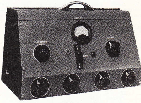
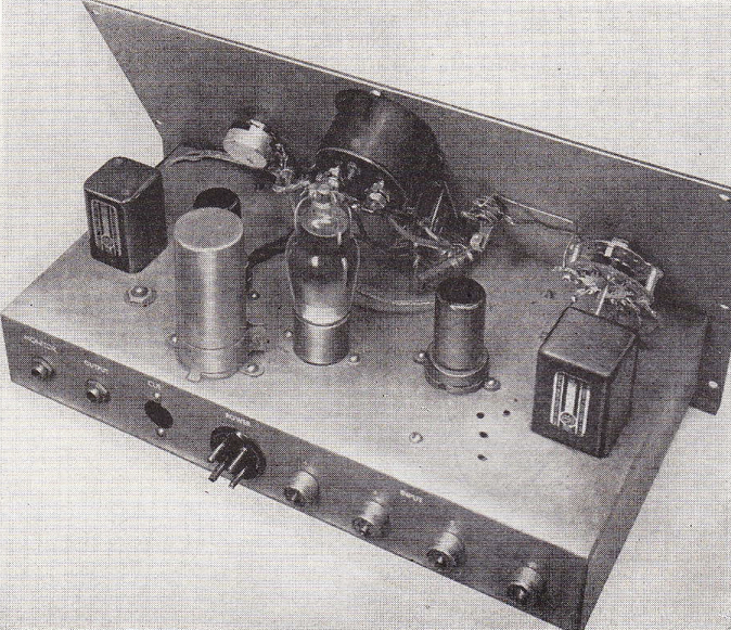
 Download a three-page article from RADIO ELECTRONICS, Feb 1949, on the subject of Build Your Own Audio Control Console. Author is Richard Dorf.
DOWNLOAD: AudioConsole1949

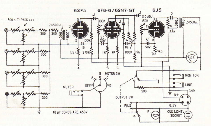
 Kinda a wacky design: it’s intended for mixing four low-z unbalanced sources, using multiple T-pads summing through a resistor network to a single tube grid (rather than using multiple input transformers and multiple tubes). Not really so practical. I’m posting this primarily in the hope that one of my readers can elucidate the output stage design for me. It seems like it must be an error, but maybe not?
 The article states that ‘any plate to line output transformer can be used,’ which means that the design does not specify an air-gapped (DC-handling) transformer. Not sure how that applies to this design. Seems like the DC would be quite different on either side of that 33k resistor? Also not sure how any signal would develop there? Is it possible because on of the secondary legs is terminated to ground? Confused. Were there any commercially-manufactured pro-audio units that used this kind of line output stage?
8 replies on “Audio Mixing Console Circa 1949”
there is 2uF cap in series with OPT primary , so blocking DC
primary is modulated by AC developing across anode resistor of 33K , combined (paralleled) with Z of primary itself
hi there. Thank you for weighing in. Your reply is difficult to understand. It seems like a few words are missing. Are you confident that this design will work? How is the value of the anode resistor calculated? Thanks – c.
OK – there is clarification : output tube is working as any other , having resistive anode loading ; AC voltage is generated across that anode resistor , when tube is amplifying input signal ; when you wire xformer primary across that anode resistor , it will see full AC voltage variation , then transform it on secondary
having 2uF capacitor in series with xformer primary is taking care of not having DC voltage (difference between Ub and Ua) through primary coil itself
take it as usually connected parafeed OPT , but referenced to Ub instead to gnd
Chris, this is a primitive but very effective mixer. It’s a passive 3×1 mixing network that then feeds what looks like a mic preamp and then a line amplifier and output transformer. It would work fine with dynamic or crystal mics, probably would not provide enough gain for three ribbon mics in front of low-SPL sources.
A later riff on this concept (no separate mic preamps for each channel) was applied by Roy DuNann at Contemporary Records in the 50’s. He realized he was dealing with high-output European condenser mics, that could put out more than a volt of signal when put in front of a loud jazz musician in Contemporary’s tiny studio/shipping room. So he used matching transformers to bring the mics into a passive mixing network, then hit each buss (left, right and echo sends) with line amps. You can listen to albums like Sonny Rollins “Way Out West” or any of the Poll Winners albums to hear the results — super-clean and no fuzz distortion from loud drums or piano.
A similar concept was deployed by John Chester when he built the sound board for the Fillmore East. John realized that a rock musician screaming into a dynamic mic produced way more signal than typical mic-input transformers could handle, and also was loud enough that mic preamp gain was not required. Same for mics put in front of a rock drummer. So John built his board with no mic preamps, a passive mixing network and very low-noise but high-gain line amps on the way out. The net result was a quite background and non-fuzzy sound for vocals, drums and whatever else was mic’d to the board.
The learning from all this applies this way to the home studio crowd — if you’re using a high-output mic in front of a loud source in a little room, you probably need to pad the mic down before it hits an input transformer on a channel strip or USB interface.
— Tom Fine
A better example is the design in the old “Audio Anthology” for a packaged mic pre for a guy that did radio for agriculture.
I think Zen Mod has it right on whether there is any current flowing through the output transformer. The capacitor will block all of the DC, so you are free to use a non-air-gapped output. The 33k resistor is kinda wacky though… Maybe this sets up a nice parallel-feed output impedance/capacitance with the 2uf output cap. Parallel feed output cap values are a bit mysterious to me.
hi there JSN. great to see that yr site is back! i had been wondering where to you’d gone. lookin forward to getting thru all yr new posts there.
now I see that jsn also mentioned parafeed
good call , of course 😉