 I’d never been particularly interested in learning solid state electronics. There just didn’t seem much point; considering that you can buy a 4-channel Sytek mic preamp for $900, there just ain’t much to motivate anyone to DIY ss kit. Tube stuff is another matter – it’s a different sound, and well-made ‘real’ high-plate-voltage, transformer i/0 tube gear is super-expensive. So I learned to make the tube gear both for my own studio and as a way to make some add’l income by custom-building for other engineers.
All that being said, there is an undeniable appeal to be able to build something useful that doesn’t require a heater circuit and the attendant 60-cycle-hum battles that come from those hi-current windings. Solid state is just easier, which is prolly why it has won-out in the world of consumer electronics, if not necessarily in the pro-audio world. In my endless diggin for ancient tubes and transformers and bakelite meters I invariably come across stashes of ole germanium and silicon transistors, and I recently decided to take the plunge and try and cross this bridge once and for all. Cos I can talk tubes and tube audio circuits up+down, but frankly I don’t know shit abt solid-state and maybe it’s time I learned.
DOWNLOAD THREE CIRCUITS FROM RCA HM-80:RCA_SS_Hobby_1968
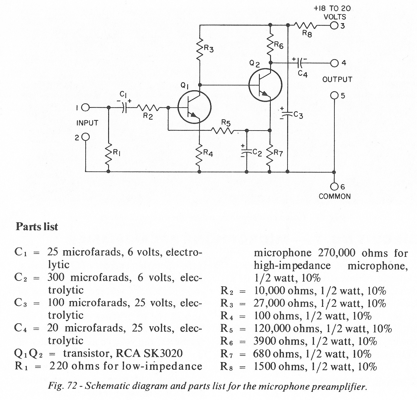
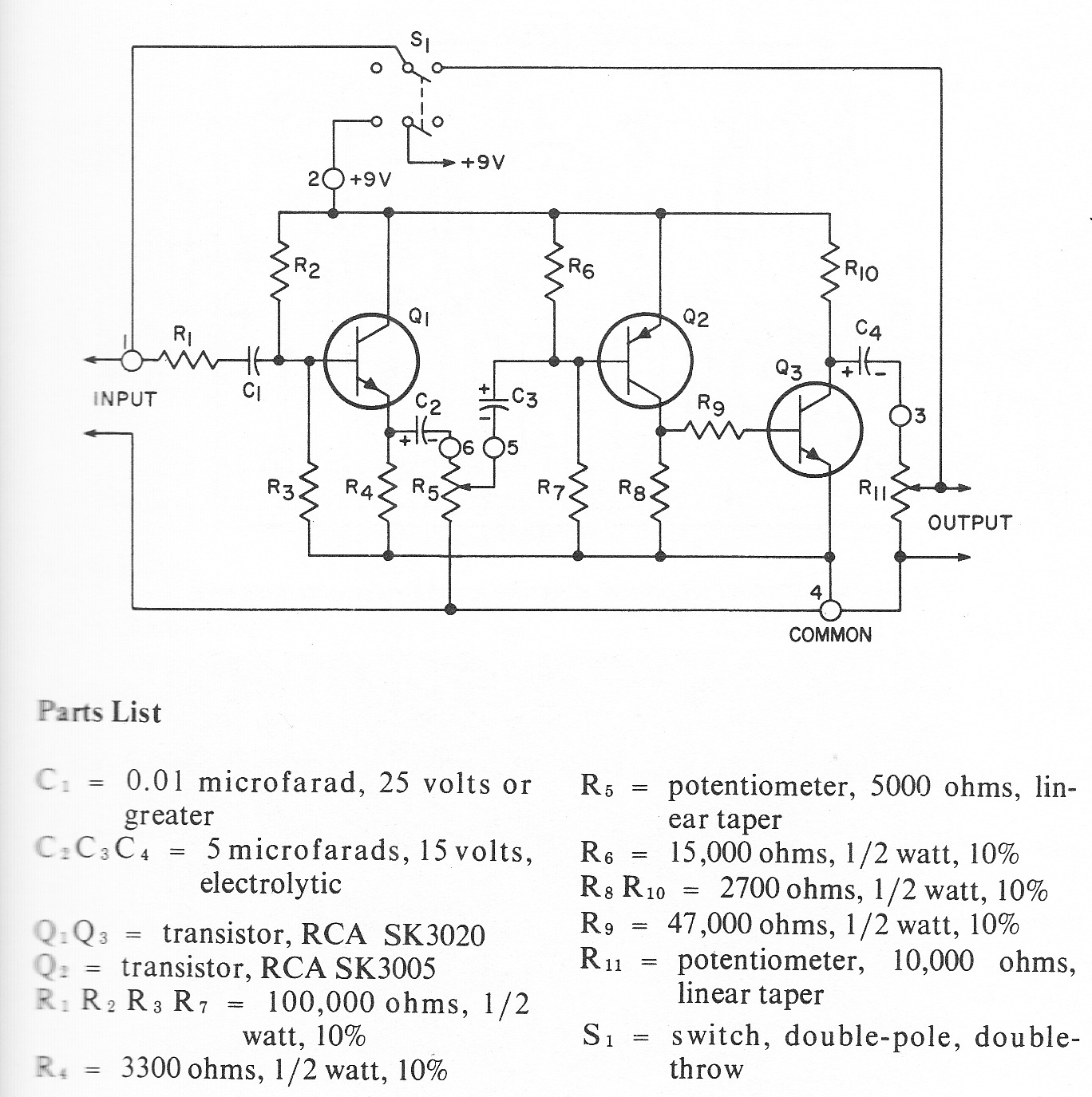
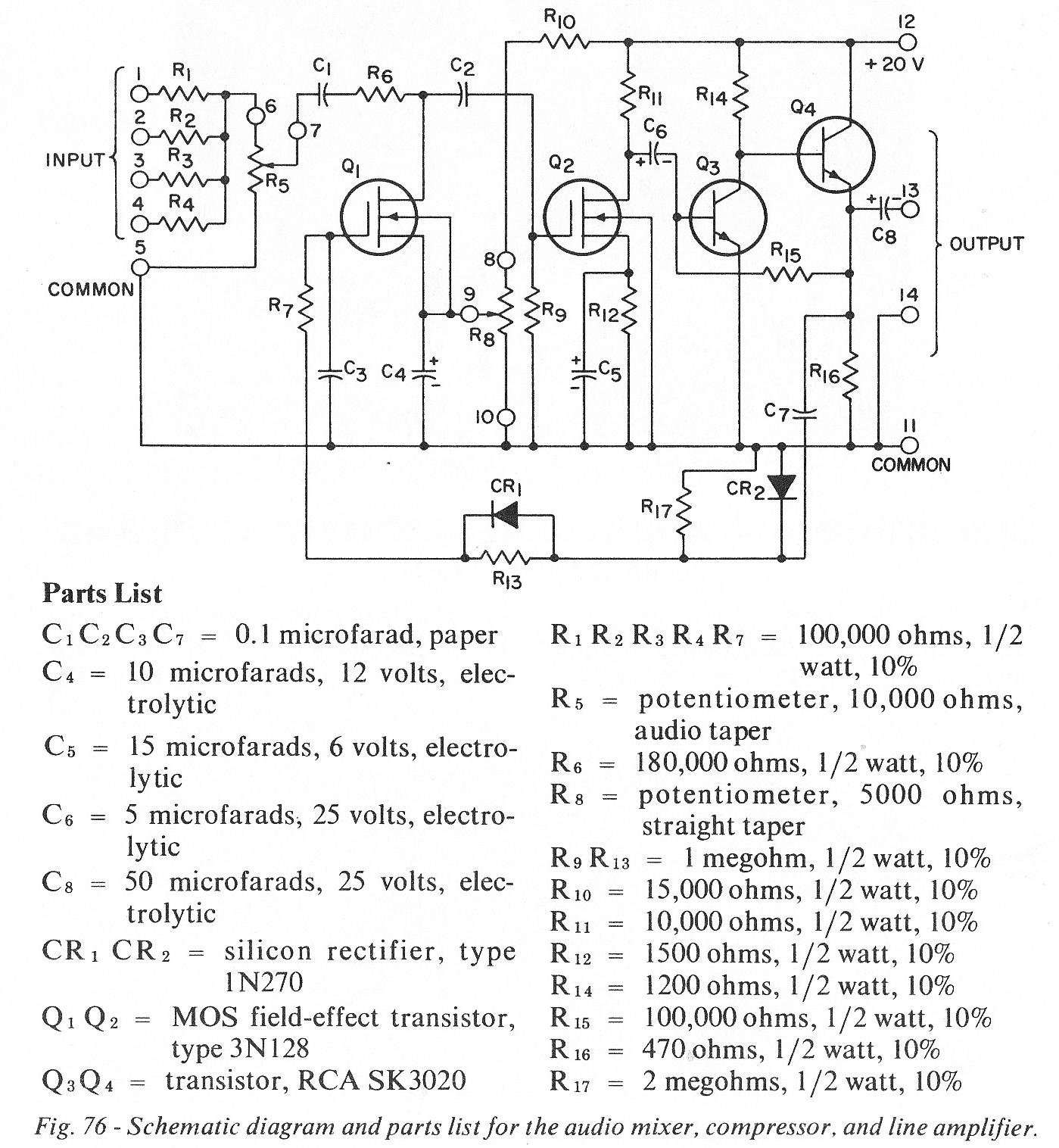
The old RCA Tube Manuals have always been my primary source of information for my tube-audio builds and experiments. The circuits that they recommend are the most solid, reliable, and practical that you will ever find. I trust them implicitly. And why not? After all, this was the company that made the tubes themselves! So when I decided to try and get into SS, I started with the RCA Solid-State Hobby Circuits Manual. In the scan above you will find a mic preamp, a line-level compressor, and a fuzz pedal. I’ll be building all three eventually and I will LYK how it goes. In the meantime, if any of y’all beat me to it, drop us a line and report back,,,
12 replies on “RCA Solid State Audio Projects c. 1968”
I think most engineers like solid state better because really doing solid state design usually takes more thinking. At least as long as discrete parts are involved. Especially with audio, everything is usually RC coupled and stages are isolated, but in solid state direct coupling rules.
So problems in one place are problems device-wide, or at least board wide.
Engineers have always used conventional current rather than electron flow, which is how tube technicians and hams and designers of tubes themselves think. And most solid state devices come in two genders:NPN and PNP bipolars, P and N channel FETs. This means bipolar supplies and balanced circuits are easy.
Bob Pease:
://electronicdesign.com/archive/whats-all-technical-reading-stuff-anyhow?
You know, with a few of those newfangled solid state things you could build a DC regulated heater supply and they wouldn’t hum like that.
I always do don. But hum can also get induced into input transformers due to those big plate/filament transfos. I agree that dc heaters are the way to go, i swear by it for tube pro audion builds.
The best walkthrough of solid state amplifier circuits I have ever seen is in this book:
http://www.amazon.com/Robert-M.-Bourque/e/B0027N9K2C
The theory and servicing of AM, FM, and FM stereo receivers
Don’t be scared off by the insane price listed in Amazon: I see them on ebay in the $15 range somewhat commonly.
ARRL manuals from the late sixties on also have a lot as do GE and RCA transistor manuals.
Did you ever build this fuzz pedal?
hey my man, did you get any of these builds together? just got a lot of solid germaniums and my interest is piqued! by the way, i love your vids on youtube; hope you find the time to do more.
-steve
hi steve. no, i have not, but thanks for reminding me. the 1/2 -completed-project-pile is pretty deadly round here…
Hey, yours is the only mention of this stuff I have found.
I’m putting together a console using the “High Dynamic Range Microphone Preamplifier” is this manual.
Check it out here:
https://imgur.com/a/nxigtky
wow that is super cool. I’d love to buy some PCBs from u if u have extras you would sell.
Did a quick simulation of the mic pre-amp using the 2N3904 models in LTspice XVII just for fun. I noted quite a bit of compression distortion at the top of the output waveform. From the FFT function, the harmonics are about 2h= -26.8dB, 3h = -34.3dB, 4h= -47.6dB, 5h= -66.4dB.
By adding a 33k resistor between Q1 collector and Q2 base the FFT harmonics improve to 2h=-56.4dB, 3h=-54.8dB, 4h=-69.9dB, 5h=-81.3dB. The cost in gain is about 5.6dB.
The distortion characteristics can be altered and further decreased by increasing the value of R2 (at the expense of more gain), but not as effectively as adding the 33k resistor.
Such a simple fix to isolate the non-linear loading of Q2. Seems even RCA didn’t understand GOOD solid-state design in 1968. No wonder solid-state has a bad rap today.
Simulation notes: SK3020 transistors are small signal Silicon NPN transistors with hfe of 150 max (reasonably close to a 2N3904). Vcc = 19 volts, Input = 1 kHz, 1 mV peak sinewave with a 600 ohm series resistance, Added Rload of 100k at the output.
Wow! I have to try your suggestions. This project has been on hold through the pandemic but I’m dusting it off now. I was getting my PCBs done by a Chinese company and shipping was a nightmare.
The gain reduction would actually be useful, these things are really hot. I have a few prototype boards to test on, I will report back.
I’d be happy to share the eagle files if anyone is interested.