
Many of my regular readers will be familiar with the Shure Level-Loc. For those unfamiliar, the basics: the Level-Loc is a brickwall limiter made by the Shure microphone company for public-address-system use (podium mics, specifically) in the 1960s. It uses discrete transistors and transformers in the signal path; it offers balanced mic-level i/o and an unbalanced consumer-level 10K ohm impedance output as well. There is an input-level control (simply a pot that follows that secondary of the input transformer) and a switch marked ‘distance selector,’ which seems to me to be a threshold control. That’s it for control. It is fairly noisy (full-bandwidth noise), even after a recap, and the transformers are not especially well-shielded. It runs off of a 9V battery. For more information on the Level-Loc, you might want to start here.
 Anyhow…seems like a toy/piece-of-junk and maybe it is, but these things have become highly coveted for use in recording rock drum performances. How much so? Well, how many other prosumer PA-system pieces are currently available as a plug-in, an API-500 series module, and a boutique re-build? (image source for above)
I recently picked up a clean Shure Level-Loc for a few dollars at a yard sale; after the aforementioned re-cap (and we’re talking about 20 capacitors here…), it was sounding like it was probably operating within its original design parameters. I was intrigued, and figured it might be worth getting it into the racks at Gold Coast Recorders to see what it could do. GCR is a big, live-sounding room, so there’s plenty of sound to get out of it with a squashed compressor. The only potential problem: the Level-Loc offers only mic-level or low-level medium-impedance output. I like to run my mic preamps directly into the Lynx convertors; so for the most direct signal, I would need a bridging amp to bring up the level and lower the impedance of the Level-Loc. It would be nice to have an output level control too, and I wanted the piece to be as physically small as possible so that it could sit directly next to the Level-Loc on a 2RU rack shelf. Here’s what I did to solve all of these problems and fold the Level Loc into the studio alongside all the other outboard mic preamps.

 ***********************************************
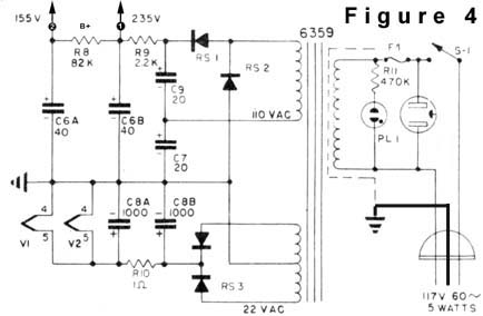
Most of the RCA Receiving Tube manuals have a schematic for some sort of ‘audio input amplifier’; I wanted one that would provide about 20db of gain as well as a very low-impedance output so that I could drive a 15K:600 output transformer easily (I used an NOS UTC Ouncer to save space). Based on this i selected the circuit above RCA manual # RC-24. One 12AU7 tube. Simple, easy. The physically smallest plate/filament transformer that I had on hand was an NOS Stancor 120v:120V/6.3V, so I used the voltage-doubler B+ supply circuit as-found in the Altec 1566 and 438: here is that schematic via Tangible Technology:
 For once i actually did not bother wiring up a DC filament supply, since the gain of the unit is pretty low. This was the right choice, as i can hear no hum at all in the finished unit. I added a 500K pot at the input jack and voila. The whole thing fit inside one of those aluminum Bud Boxes that some folks use for DIY’ing guitar effects pedals. I left the power transformer bolted outside the unit on the rear; it’s always a good idea to keep power transformers away from audio transformers if you can. Here’s the interior of the unit:
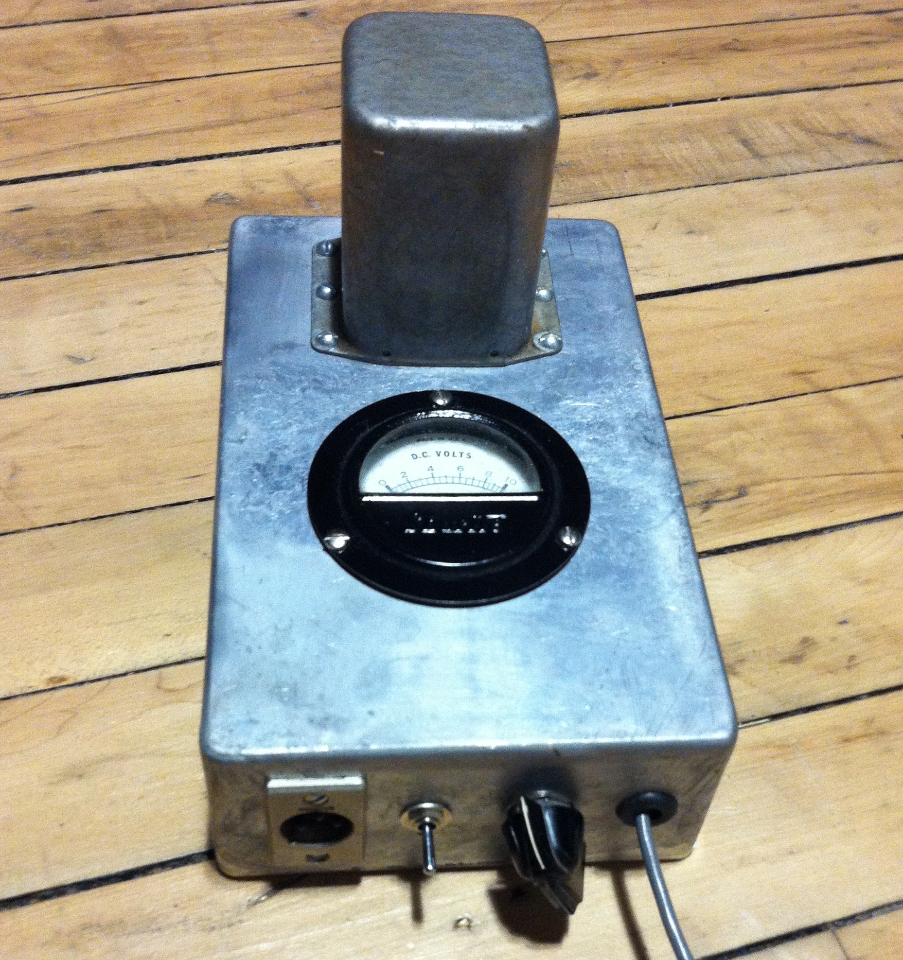
 …and below you can see the finished piece. Not my finest piece of industrial design but it does the job. I put the 1/4″ TS input on the front of the unit so that I can use it as a DI input for Keyboards ETC if the need arises. The circular grill on the top surface of the piece is a heat-vent positioned directly above the 12AU7 tube.
 The unit performs well, especially considering that there are only two stages of filtering in the power supply. I always use four stages of filtering in the equipment that I build for customers, with at least one choke; I was curious this time to see how the basic Altec B+ scheme worked, though, and it seems just fine! People love their 1566s and 438s so fukk it. Good enough is sometimes good enough…
 Above, the two units side-by side. So how does it sound? TW and I were putting down live drums on a track at GCR and here’s the result we got.
First, the drumbeat: close-mics only: CloseOnly
Here’s the same mix, but with the Level Loc signal added: in this case, the Level Loc was amplifying a figure-8 ribbon mic 20 feet from the kit, with the null of the mic facing the kit; the waveform was then re-aligned to eliminate some of the delay: withLevelLoc
And finally, the Level-loc signal only: LevelLocOnly
The Level-Loc is aptly named. Regardless of what you put in – a baby’s breath or an atomic blast – you get the saaaaame level out. Zero dynamics. It’s pretty uncanny. And a great sound for heavy rock drum beats. This is the 2nd track that I have used it on in a week and I think it will continue to get a lot of use at the studio. The output of the balancing amp is a little low – even with the input attenuator all the way open it cannot quite get to full level via the Lynx convertors. It’s good enough, but it could stand to put out a few more DB. If you build one of these devices for use with your Level-loc you might consider using a 15K:60K interstage transformer at the input to get a little bit more level out of it; or re-bias the two stages in order to use a 12AT7 instead of the 12AU7.
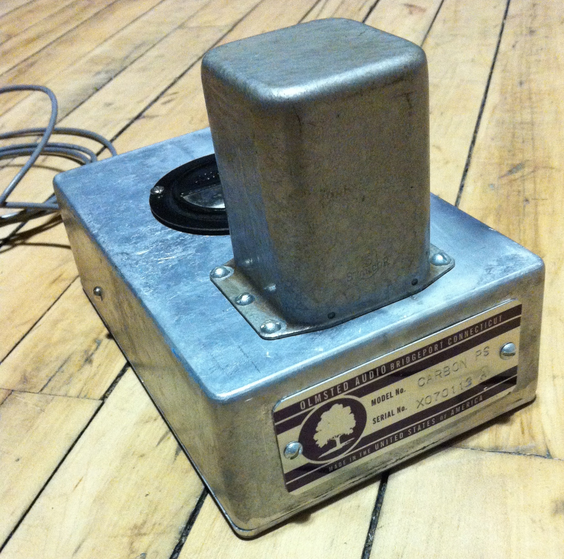 Here is a one-of-a-kind unit using a re-purposed Thordarson transformer. IT works great, and the vintage Shurite (made in New Haven CT!!!) DC voltmeter is a bonus.
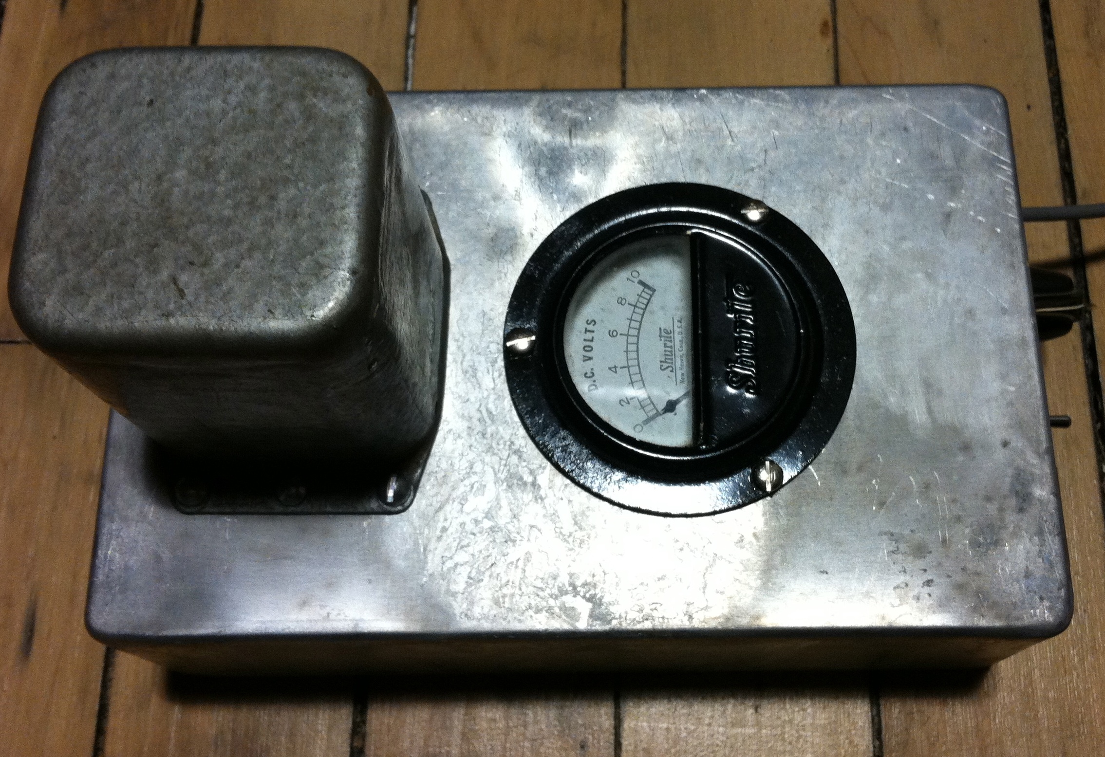
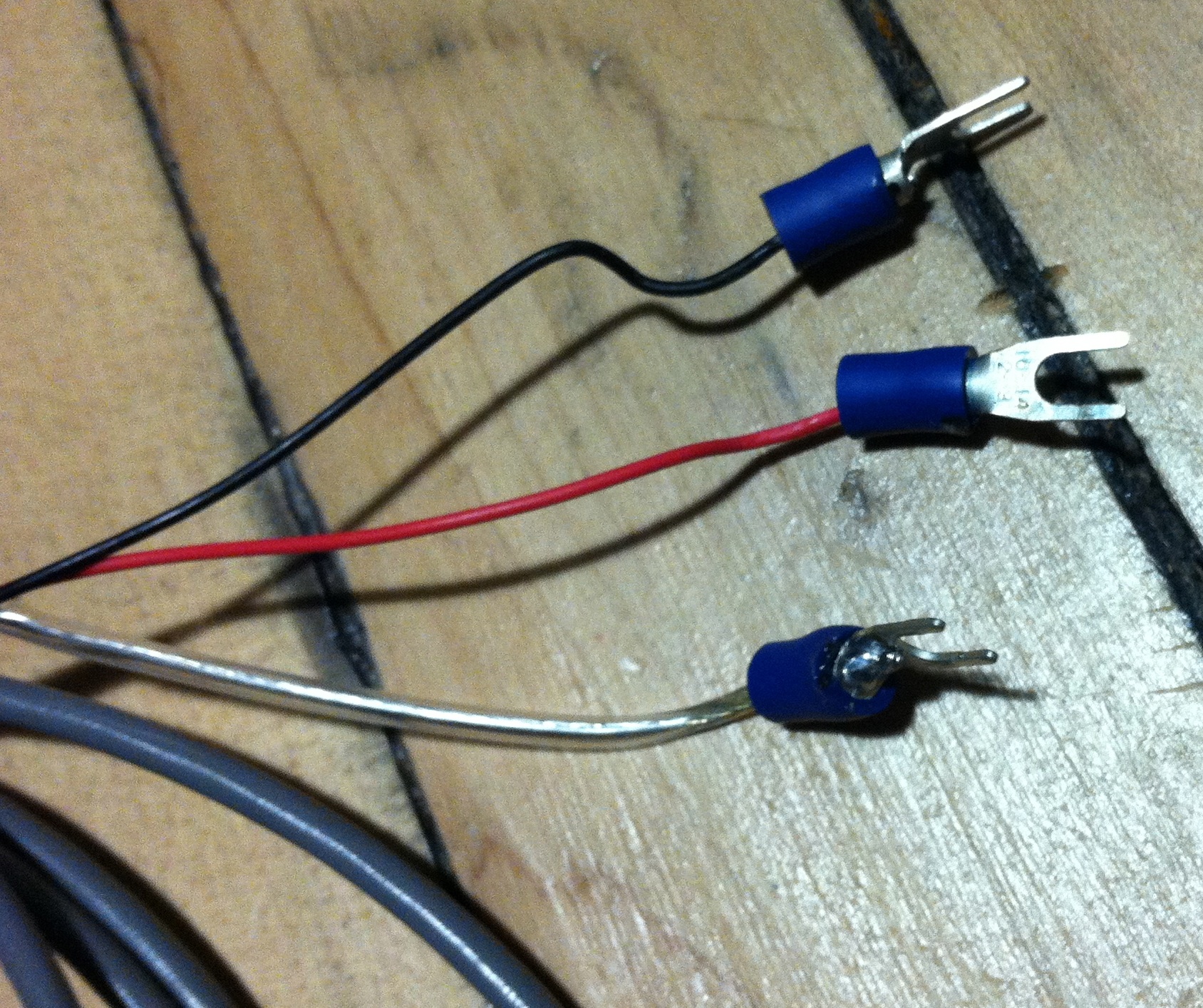 On the ‘business-end’ (topmost image) you can see XLR output jack (for connection to the input of your mic preamp), on/off switch, pot for controlling the DC voltage that mic receives, and at right the cable-exit for the seven-foot cable harness that connects to your double-button carbon mic. At right: red and black wires connect one-to-each button, and the clear wire connects to the metal shell of the mic.


