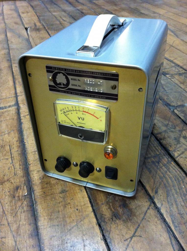
 So I was flipping through Recording The Beatles recently and I was reminded that I had yet to make one of those famous EMI console preamps. As luck would have it, we were hit with a pretty major blizzard and I had a few days with nothing much to do. The preamp turned out great, I love the fast (fast for a tube/transformer circuit, that it…), assertive sound of it, and I will definitely be making more of these things. I’ve been using it primarily for tambourine (with a vintage Senn 409), acoustic slide guitar (with an Altec 660B), mandolin (with my Audio-Technica 813) and acoustic rhythm guitar and shakers (EV RE15).
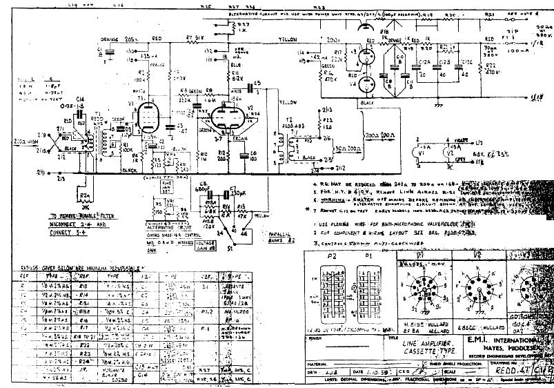
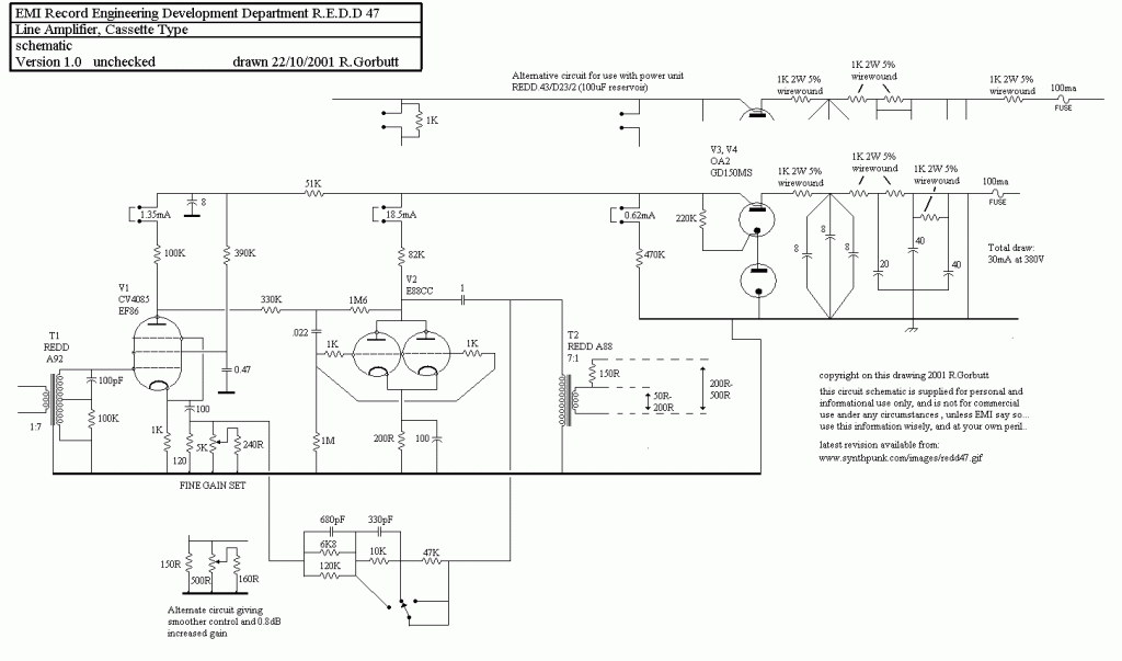
Here are some of the resources that I used to build the device. I apologize to whoever originally posted these documents for my lack of attribution; I DL’d them so so long ago that I can’t recall where they came from.
DOWNLOAD: EMI-REDD47
Another Download: REDD47AmpSchem
There is a real lack of consistency among these documents, and no I am not going to offer a ‘corrected’ schematic; that being said, if you actually have the where-with-all to fabricate one of these things from scratch I think you will do just fine with the same materials that I started with. And if you don’t want to do it from scratch: no problem! Just visit these dudes. (n.b.: I have never used a drip electronics product personally, so I can’t vouch for them; that being said, they are extremely popular and seem to know what they are doing).
A few build notes
I used my usual Jensen input transformer (click to DL info) and Edcor output transformer. The thing sounds great overall, so I recommend these, at least for a first-build of this circuit. Why spend more?
Very important: this circuit uses a lot of negative feedback. There are also a lot of capacitors in the feedback path. Each capacitor contributes some hi-pass filtering, which should be below audio range, BUT… if the capacitor values don’t all ‘play -nice,’ you could end up with so much phase-shift in the sub-audio region that there is 180-degree phase shift in the sub-audio region and you will have a device that ‘motorboats,’ I.E., your ‘negative feedback loop’ is a POSITIVE feedback loop aka a fkkn oscillator. I had this problem initially. The device worked fine, seemed to sound good, but at the lowest gain setting (aka the setting with the MOST negative feeback, get it????) I was seeing some 10hz signal pretty prominently in the audio files. I guessed that this was due to the fact that I used a 47uf cap by the cathode of the input tube, rather that 100uf that is specified. I made the correction and viola problem solved. HERE’S THE SHORT VERSION: with this much feedback, component values are critical. BTW, who knew that Apogee A/D convertors work so well at 10hz???
The Redd 46 has a three position gain-switch, and also a ‘gain trim’ control that does very very little. Think of it as a ‘channel matching control’ rather than a level control.
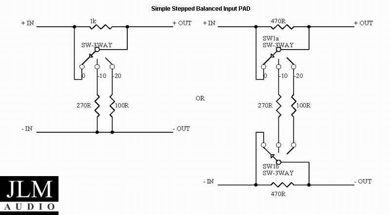
Because of the lack of gain control, and the fairly high minimum gain setting, the Redd 46 really needs pads to be used in the studio. Since I did not leave enough panel room to add i/o pads, I have been using it with some external 10 and 20 db ‘XLR barrel’ pads. Depending on the amount of drive and crunch that I want in the signal, I have been adding the pad either before or after the preamp (or both!) before the signal hits the convertor. Therefore, the next time I build one of these, I am going to include two two 3-way (0-10-20) switched pads in the device, one before the input trans and the other after the output trans. I highly reco that you do the same. I generally use a pad design similar to this one suggested by JLM audio; never had a problem with it.
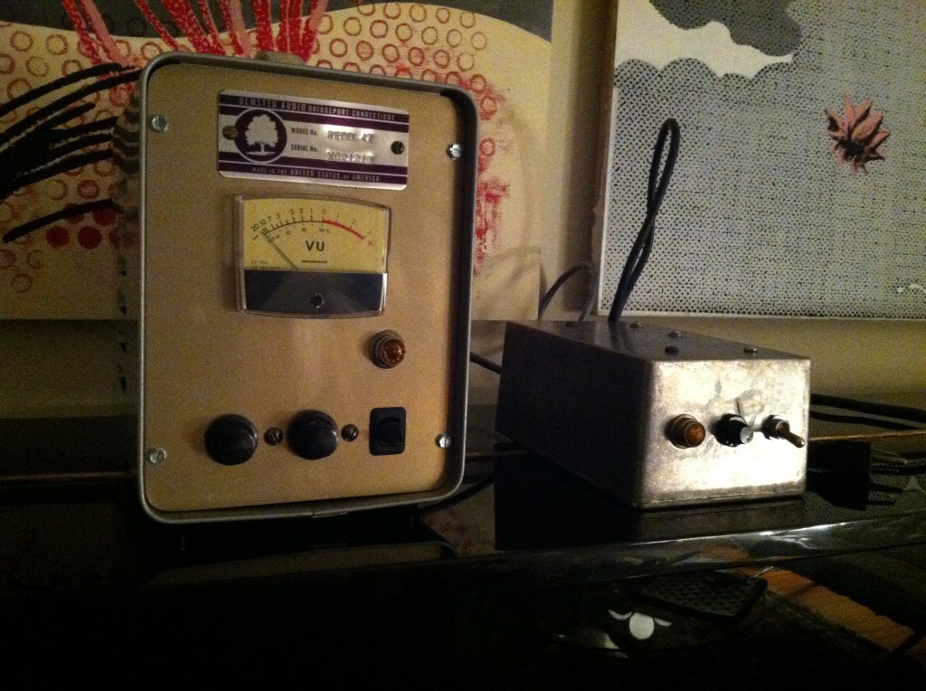 Above: another shot of my REDD 47; the box on the right is the power supply; basic voltage-doubler (ala the Altec 1566) with tons of filtering and a choke for the B+ and DC filament supply. Connection is by a 4-pin amphenol.
I have gotten a lot of questions regarding the enclosure used for the audio chassis: it’s a BUDD enclosure of some type, I can’t recall the exact product name; it was dead-stock from a local distro, last one they had, and I am guessing that it was manufactured in the 70s. No idea where to get more of them. If you know, please drop us a line…
