For my non-technical readers: a phono preamp is a device which does two basic things: 1) it equalizes the program that the phono cartridge picks up off the LP record, basically by boosting the low-end and cutting the high end, with this action centered at the fixed frequency of 1K hz (for full details on the ‘RIAA compensation curve’, and why it is necessary in the manufacture of LP records, read here); 2) secondly, a phono preamp must amplify the signal of the phono cartridge to roughly line-level (IE., the level that would come out of a CD player or VCR) and also deliver this signal at a low enough impedance such that it can be in-put to any receiver or consumer amplifier that it might encounter. Here is my attempt at a self-contained version of the phono pre-amp section from the Marantz 7 hi-fi preamlifier.
 (web source)
I’ve never heard an actual Marantz 7c in action. Considering that this dude, who does not seem like a total flake (based on his sales record) is selling one for $4,999 on eBay, I had to assume that it sounds fine (at least). Marantz is one of the legendary American Hi-Fi brands from the ‘Golden age of Hi-fi,’; their original line-up of products (before Saul Marantz sold the company) are widely lauded for both their sonic and aesthetic traits (see here for previous Marantz coverage on PS dot com).
 (web source)
Above, the schematic that I used for this build. It is a simplified version of the Marantz 7C, omitting such features as pre-RIAA disc compensation curves and bass/treble controls (for the complete 7C schematic, see here). The only change that I made to the audio section is that I added a 1K resistor between the signal output (the .47 cap) and the output jack. Couldn’t hurt, right? The phono pre-amp section consists of the three triode stages that you see at the left. The three stages to the right are additional make-up gain that follow the overall balance and volume controls. Important to note: the output of the phono stage is a cathode follower. This means that the signal is derived from the cathode of the tube rather than the plate. This results in very little voltage gain (in that particular stage) but… also… pretty low impedance. Which is what I wanted.
 Above, the RCA RIAA phono preamp as published in several of their “Receiving Tube Manuals.” I have built this RCA circuit before; while excellent-sounding, it does require an additional stage of amplification (I used a cathode follower circuit) to lower the output impedance of the device if you want to be sure it will ‘play-nice’ with all yr other kit.. Notice the note at the output leg of the circuit: “220000 ohms minimum.” Wow! That is very high impedance. The only devices that this thing should feed are either the grid of another tube or possible a FET. This condition makes the RCA circuit (on its own) insufficient as a stand-alone device. And RCA did not really intend this to BE a stnd alone device; rather, they intended that you would build this into an amplifier where the circuit could directly feed the input grid of a preamp tube. The Marantz 7c circuit, with it’s third cathode-follower stage, does not have this limitation.
 Above, the interior of the completed piece (audio chassis). Note the French SOLEN coupling caps (my favorite due to good performance, reliability, and small size) and single ground buss (the piece of copper that runs along the lower edge). RCA used the single ground buss technique in most of their broadcast equipment, and AFAIK, this grounding style cannot be beat for performance and ease of manufacture.
 Above, the interior of the power supply. I built the unit into two seperate chassis: audio and power supply: this was an aesthetic preference of the customer, and it also makes good sense when you are dealing with the miniscule audio voltage that emanate from a phono cartridge. Sure enough, the finished piece exhibits no (z-e-r-o) hum whatsoever. I did not follow the Marantz 7C schematic for the power supply; I just built what I though was neccessary: a DC supply for the filaments and a B+ chain with 4 stages of filtering (no choke). I used an NOS RCA power transformer that was a lil’ bit too exuberant for the 280V B+ requirement, hence the large-ish 15k ohm resistor near the bottom (the Marantz 7c schematic called for a 3.9k ohm in this position). When all was said and done, after experimenting with a three different resistors in this position, I was within 1% of the voltages specified in the schematic.
So how does it sound? Very good. Compared to the RCA phono pre, it rejects WAY more RF; it is very rich, extremely quiet, and the low-end response is so, so much better than the phono pre amps that come built into modern stereo receivers. I QC’d the piece with a good cartridge and a clean pressing of TUSK and it was “as Lindsey Buckingham intended it to be heard.” If you are thinking about making a tube phono preamp, give this one a try; build cost is very low and it went together very fast with no hassle.
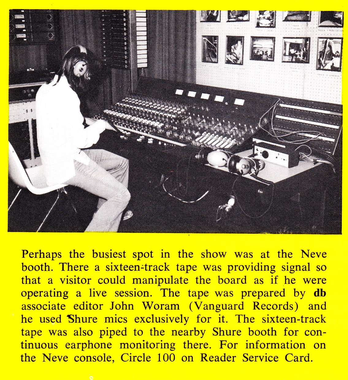
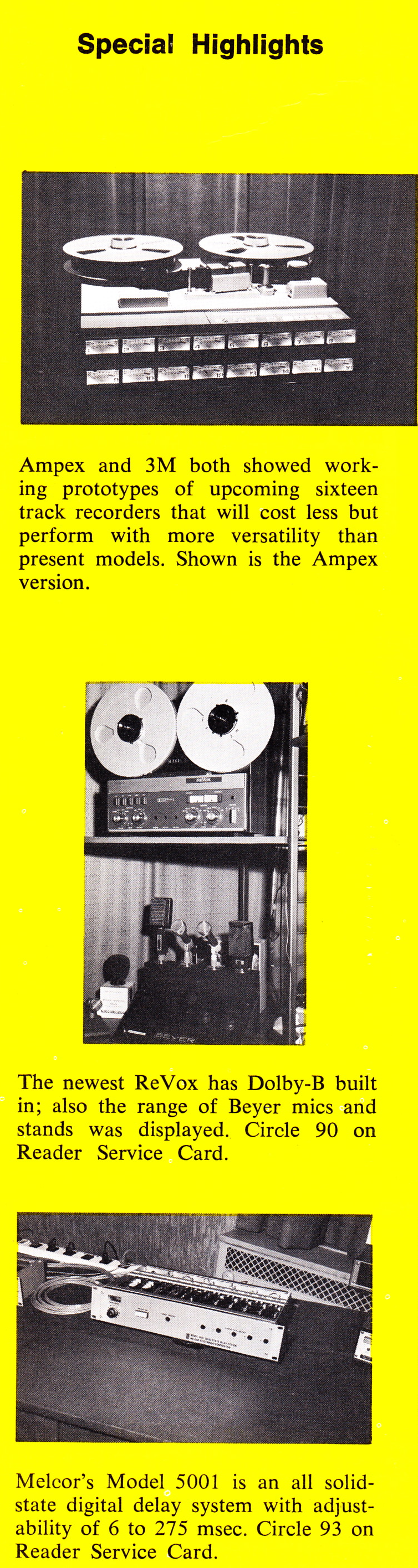
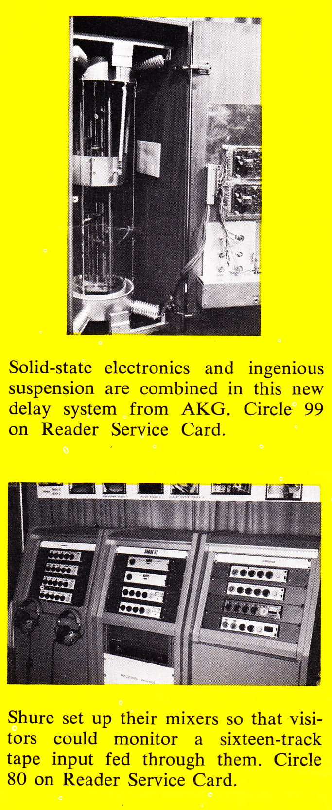
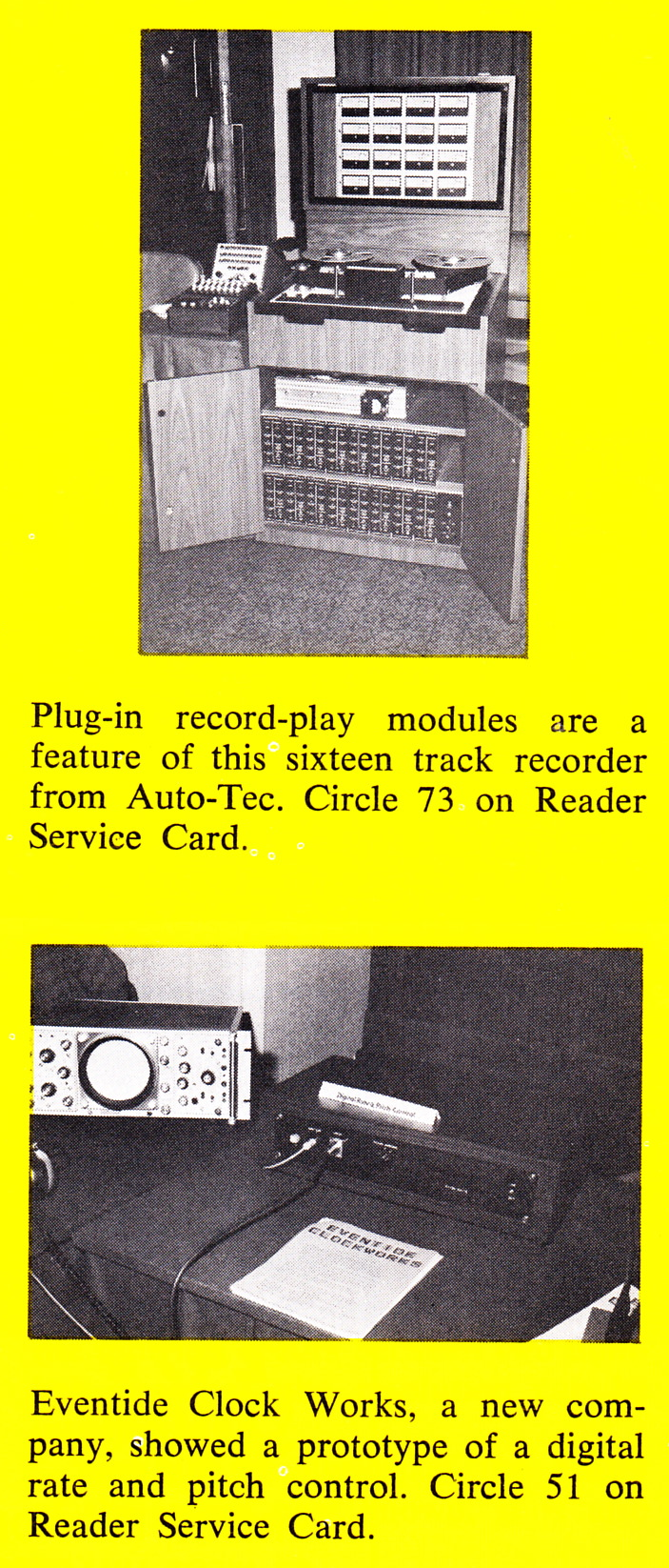
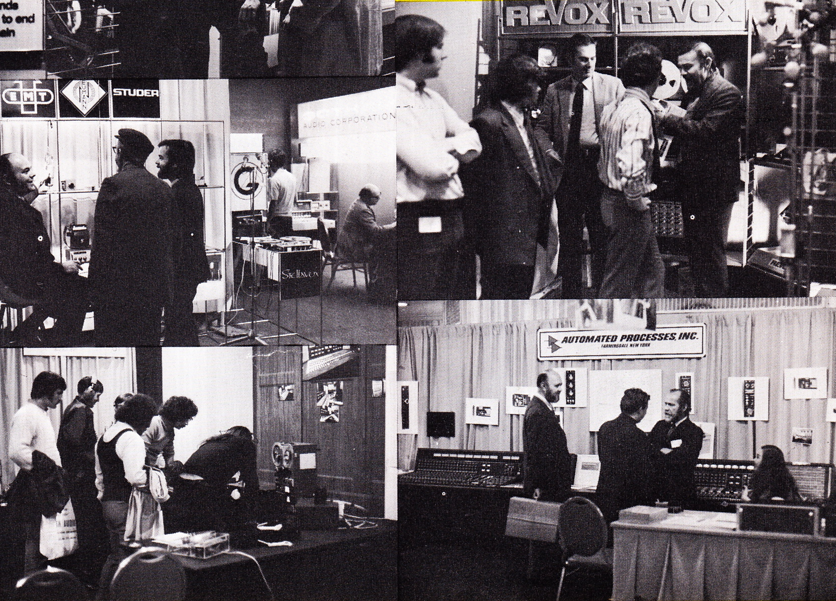 ,,,and today, perhaps unsurprisingly: some of the new kit unveiled in 1971 at the NYC AES show, also via DB mag. Of note: Auto-Tec, Scully, Ampex and 3M intro’d new 16-track machines, Neve made a push for a new console (would this have been the series 80?), AKG introduced the BX-20 reverb, Melcor showed its model 5001 electronic reverb (anyone???), and a new company called Eventide introduced a digital pitch-shift device! The Neumann U47-fet and Sennheiser MHK-815 mics were introduced, as were the Marantz 500 and Crown M2000 power amplifiers.