Categories
Antique Hi-Fi Archive

Terminal Radio 1949 Recording and High-Fidelity Catalog

Download the entire 16pp TERMINAL RADIO Recording and Hi-Fidelity Equipment catalog:

DOWNLOAD: Terminal_Radio_1949_Catalog

Products covered, with text, some specs, and photos, include: Brush Magnetic tape recorders BK414, 710B, 810, and 808 Twin-trak; hi-fi tube amps from Brooks (10C3, 12A3), Meissner 9-1093 tuner amp and  9-1091C, RJ-12A tuners; tuners from Browning, Many Stephens Tru-sonic speaker systems and drivers including P-63HF, P-52A, P-52LX, P-52HF; Hi fi amps including Scott 210-A, Fisher SA-1, Altec Lansing 323B, Newcomb HLP-14A, Bogen PX-15, Thordarson 31W10AX; Bell 2122, Masco MA-12EZand Rauland 1825; FM tuners from Espey, Meissner, Craftsmen, Howard; Customode hi-fi furniture and cabinetry; Altec drivers including the 603B, 600B, 400B; Jensen drivers incl. JRP40, HNP-51, JAP-60; Cinaudagraph speakers CIN-12A, 15B, 15C; and so, so, so much more.

Follow the link below to READ-ON,,,,

Categories
Custom Fabrication

Stereo Audio Power Amplifier (Home Use)

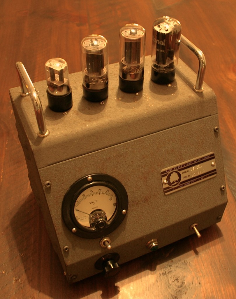
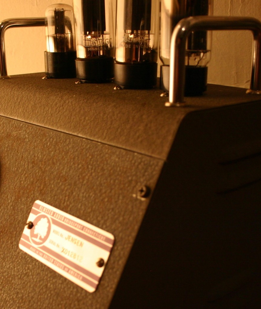
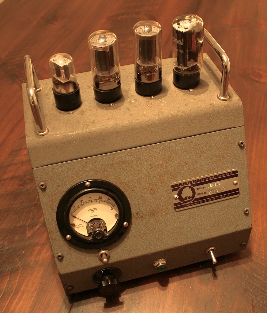
Above, a recently completed piece.  It is built on one of two identical NOS cabinets that I pulled from a Milford CT basement some years ago.  Aside from the unusual enclosure, this is the same “iPod” stereo amplifier that I have built before; see here and here for other examples.

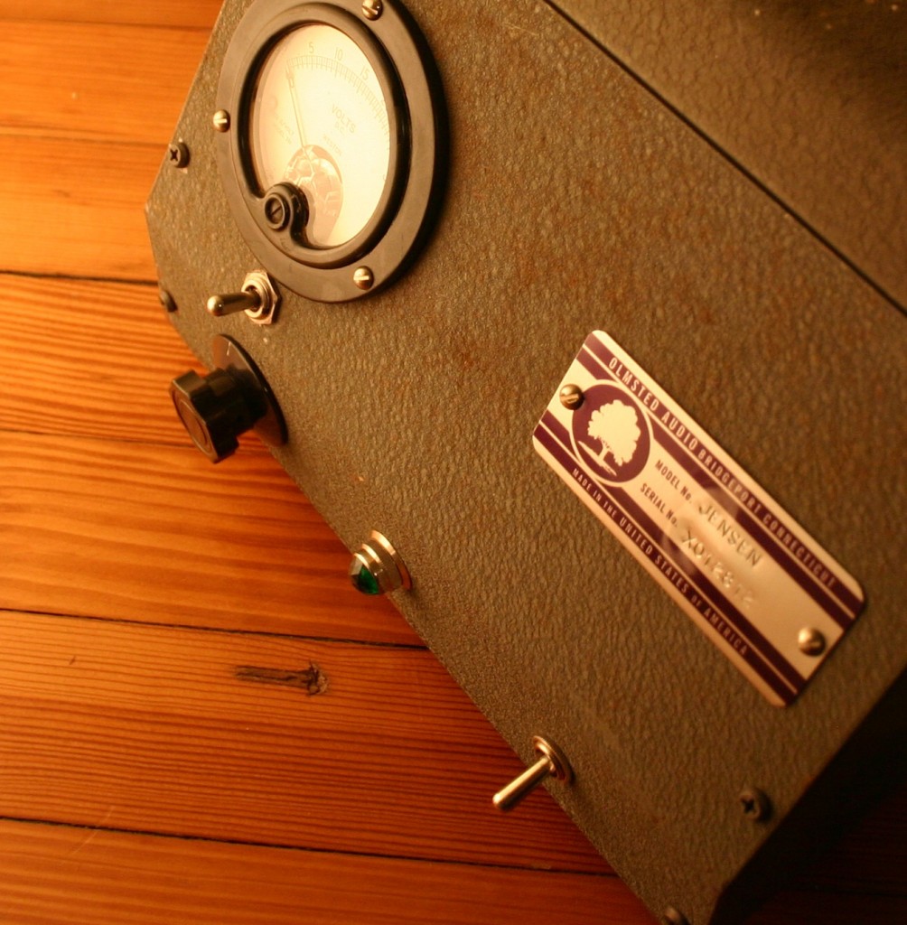
The meter (0-30V DC) is a bias meter for the output tubes.  The switch below selects left, right, or off position.  This will help alert the user as to an appropriate time to replace the output tubes.  The circuit is very simple: RCA jacks on the back feed a 100K dual-pot, then on to a 6SL7 (one half per channel) and then to a single 6L6 per channel.

Inside the cabinet are a very large EDCOR power transformer, two paper-wrapped output transformers, a choke, and a whole bunch of filter caps. Rectifier is a 5U4 and filaments are AC.  Electronically it is nothing special but visually it is one of my favorite pieces yet.

Categories
Uncategorized

The Williamson Amp, part one

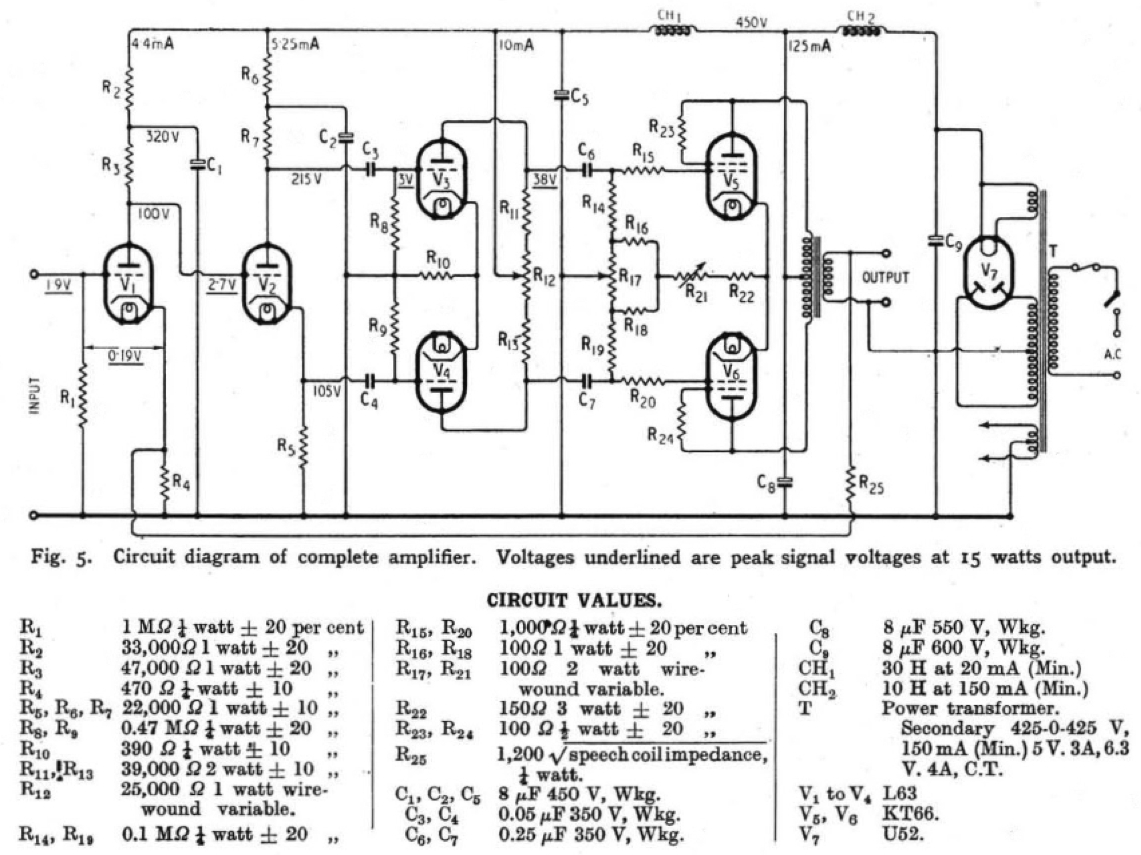
The original Williamson hi-fi amplifier schematic as published in “Wireless World” magazine (UK) May 1947.  

The Williamson amplifier is considered one of the earliest hi-fidelity audio amplifier designs.  It is certainly one of the most popular audio circuits ever developed for DIY’rs.  Without fail I seem to turn up at least one home-brewed Williamson every year at the local estates+fleas.  A PS Dot Com reader from the UK sent us the original articles from “Wireless World” as published in 1947.   I have yet to build a pair of these myself, and the idea of starting ‘from the top,’ as it were, with the original design, is appealing.  A few things to note: check out the provision to balance the driver stage, and separate bias level and balance controls for the output stage.  Also: check out R25: the formula for determining the feedback loop resistor.  I wish every schematic included this notation.   NB: the ‘L63’ valve is simply a 6J5 – aka, one half of a 6SN7.  the ‘U52’ rectifier is a 5U4 or equivalent.  ‘KT66’ is a better-performing 6L6; feel free to use 6L6 or 5881 if necessary.

Categories
Antique Hi-Fi Archive

Mystery Amp Circa 1955: Mystery Solved. Anyone have a schematic?

*UPDATE NOV 2016:  please read thru the comments section!  In all likelihood, this is in fact an original Mirko Paneyko piece, which means I am a huge A-hole for selling this thing for $180 on eBay in 2012. I only learned about MP in 2016 via a huge collection of old journals I purchased.  He was a titan in the audio field, and certainly one of the most interesting historical figures in the Bridgeport area in the mid 20th century.  Read his NYT obit here. – ED

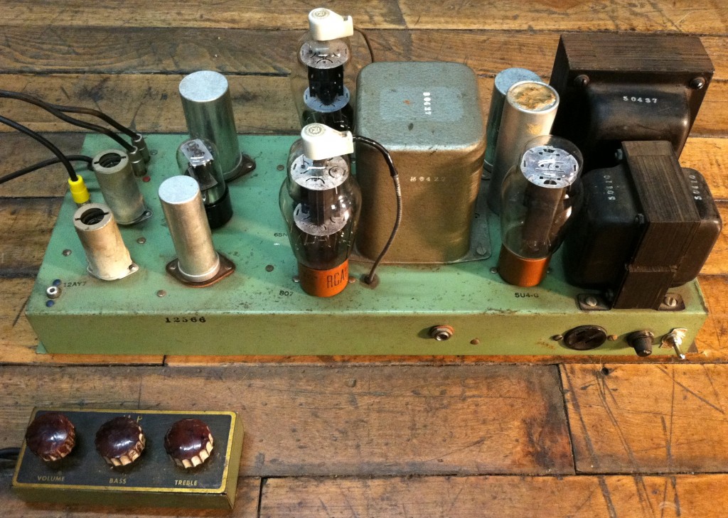
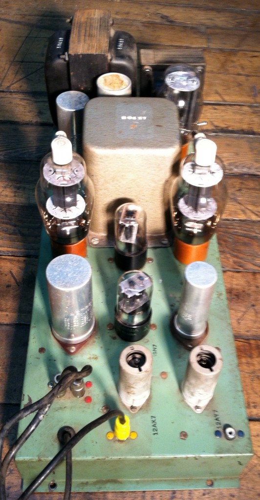
  I picked up a big pile of old audio equipment this past weekend; notable items included a Shure Level Loc, a massive Bogen tube pa head, a kit-built Acrosound ultralinear 5881 amp, and a Gibson acoustic gtr case from the early ’60s (no gtr).  Also included was the mono amplifier shown above.  It’s a push-pull amp, cathode biased 807s, with 6SN7 driver and phase inverter; there is also a 2x 12A_7 preamp section with this ‘remote’ control section attached via 10′ of cabling…

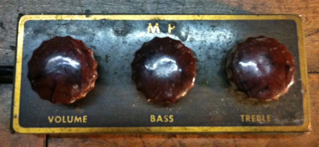
After a little cleaning, the amp actually works fine if I remove the ‘remote’ and input directly into the final 12AX7 stage prior to the phase inverter.  As far as actually using the remote, well, I can’t quite figure out what sort of patching needs to be inserted with the two RCA jacks and one RCA male plug coming out of the face of this thing.  It’s a little bewildering.  If anyone can tell me who made this amplifier, I imagine I could find the schematics somewhere.  There are no markings on the unit anywhere besides an inked serial number inside the chassis and the letters ‘MP’ on the remote.  I am sure that this is a factory-wired unit, as there is tamper-paint on every solder joint.  BTW, I added the on-off-switch and the IEC socket on the side, so don’t let those two details derail your ID’ing efforts.  I am guessing that this a circa 1955 unit as the 12AX7 was only introduced in 1953, and the 807 craze was in the process of winding down by ’55…  so we’re likely looking at a unit made between 1953 and 1958.  Any ideas, please let me know.  This thing is 95% of the way to full operation and I’d like to get it running strong again.  It’s a tremendous looking piece, and it has a lot of volume.

*************

*******

***

Updated: the mystery has been solved.  This amplifier was built by the Saulnier Music Service of Columbus, Ohio; so sez the son of the man responsible.   Read the comments section for the full story.  I am still in a need of a schematic (or even just a manual?) for this thing so that I can figure out what do do with the assorted preamp jacks n’plugs.  According to our poster, this circuit came from a transformer manual; which would likely mean a Stancor audio-manual circa 1954.  Anyone?

Categories
Custom Fabrication

Sound From A Glass Box

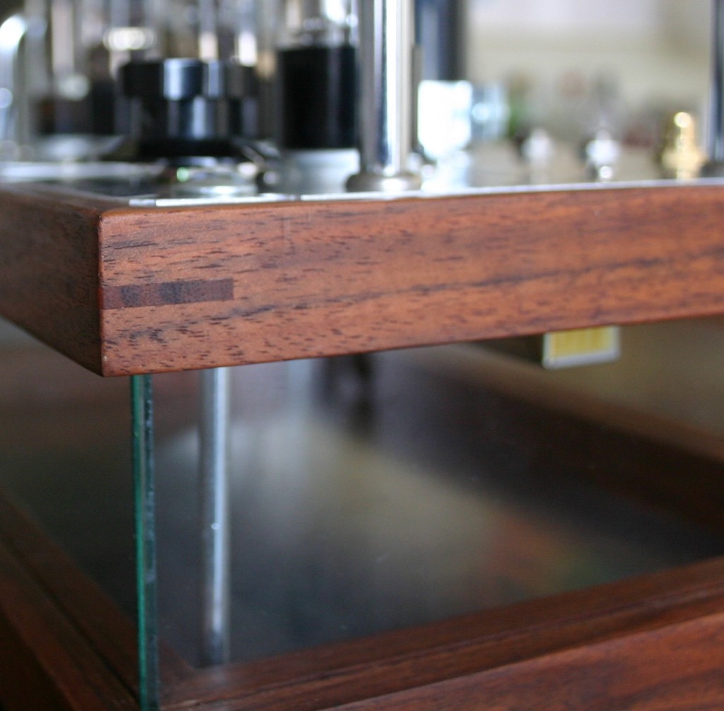
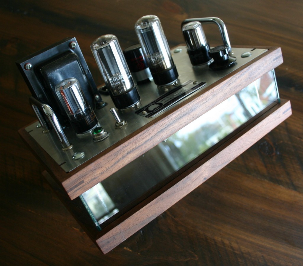
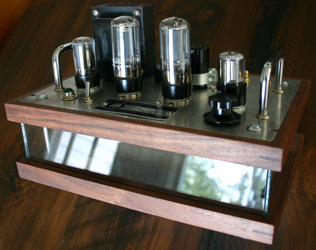
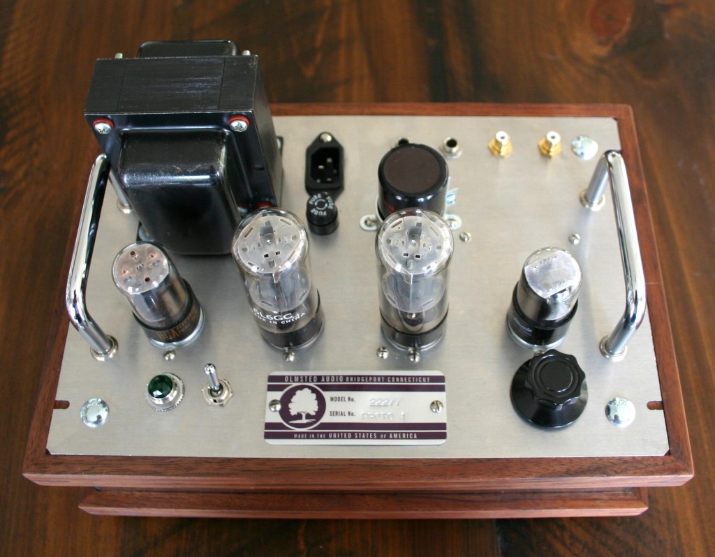
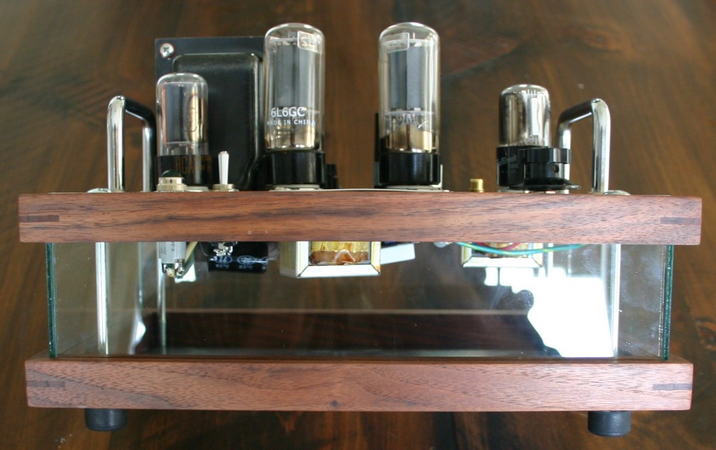
This design project began with the goal of crafting an entire amplifier that echoed the form of a vacuum tube itself.  See here for example of the intial execution.  Thanks to cabinet-maker N.N. for the beautiful walnut frames.

The 22277 is a two-channel audio amplifier for home music-listening.  Power output is approximately seven watts per channel.  Each channel uses 1/2 of a 6SL7 twin triode and one 6L6.  The rectifier used is a 6AX5.

Volume control is provided.  Inputs are via twin RCA jacks and speaker outputs are via 1/4″ jacks.  The relatively high gain of the 6SL7 tube allows the unit to be driven to full output from any line-level source (E.G., radio tuner, DVD player, iPod, etc).

Categories
Uncategorized

Mullard 520 Power Amplifier c.1956

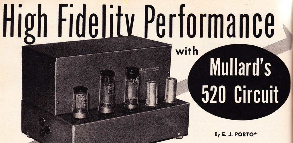
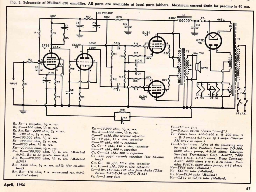
Download a four-page article from “Radio & Television News” 4/1956 regarding the Mullard 520 power amp:

DOWNLOAD: Mullard_520_amp

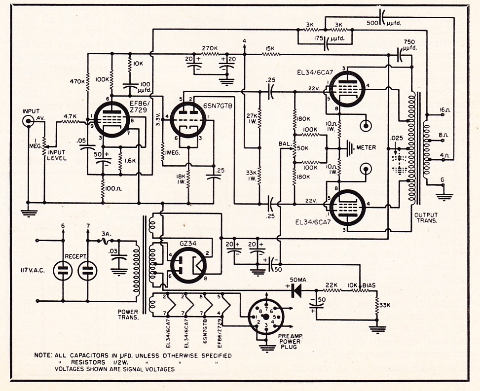
American industrial titan RCA offered schematics for a variety of tube-audio equipment in the back pages of their many “receiving tube manuals.”  Mullard, a prominent British maker of vacuum tubes, similarly published a book entitled “Mullard Tube Circuits For Audio Amplifiers”  (h.f. “MTCAA”). The designs are quite different from RCA’s, as Mullard promoted different tubes:  EL34 rather than 6L6/5881; EL84 rather than 6V6; GZ34 rather than 5U4; and EF86 rather than 5879.   The MTCAA also offered extensive plans for the fashioning of the actual sheet metal cabinet and transformer-cover.  The four-page article I am offering here is quite different from the one in MTCAA, but either will get you on yr way to building this unit.

This design promises 35 watts from a pair of cathode-biased EL34s.  It does require an ultralinear (IE, with screen taps) output transformer with a 16ohm winding for the negative feedback loop (such as this EDCOR model), but other than that it’s all very basic parts.  Now if I could find some good cheap EF86s…  Anyone try the new $17 Electro-harmonix EF86?

BTW, The Mullard book is still readily available as a reprint; well worth the $17 cover price IMO.  There is a circuit for a 3-stage ‘mixing preamp’ featuring EF86 pentode inputs with a 12Ax7 on the back end, the second triode of the 12ax7 wired as low-impedance cathode follower…  pretty tempted to try that one…  anyhow, you can buy ‘MTCAA’ at Amazon Dot Com or at Antique Electronics.

Categories
Antique Hi-Fi Archive

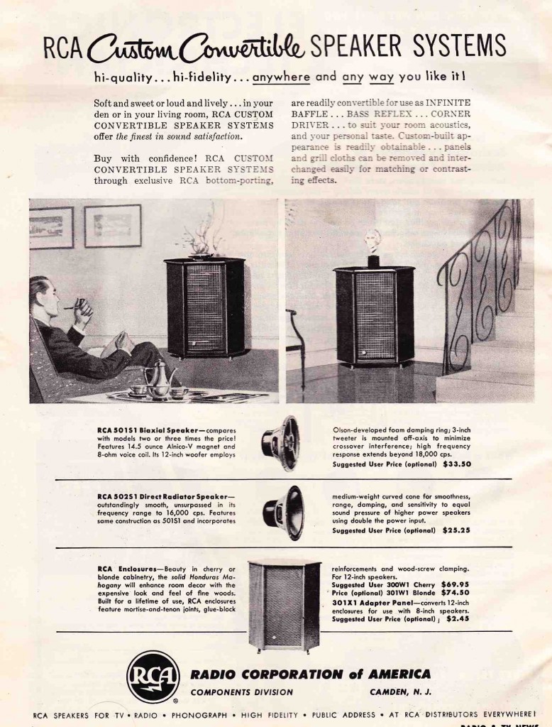
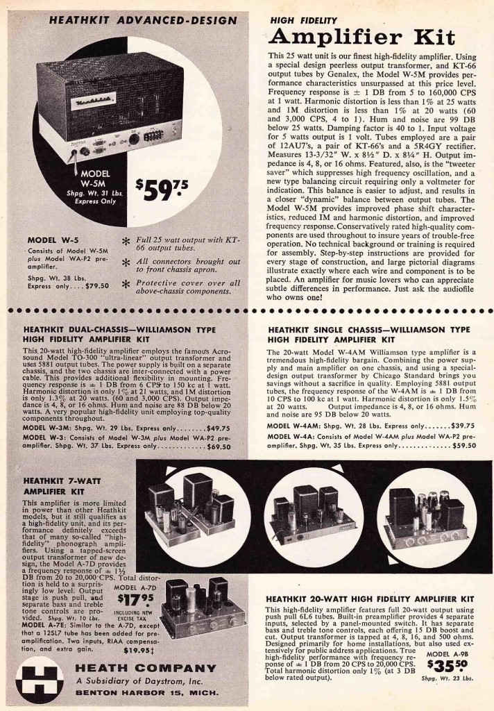
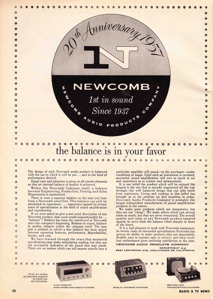
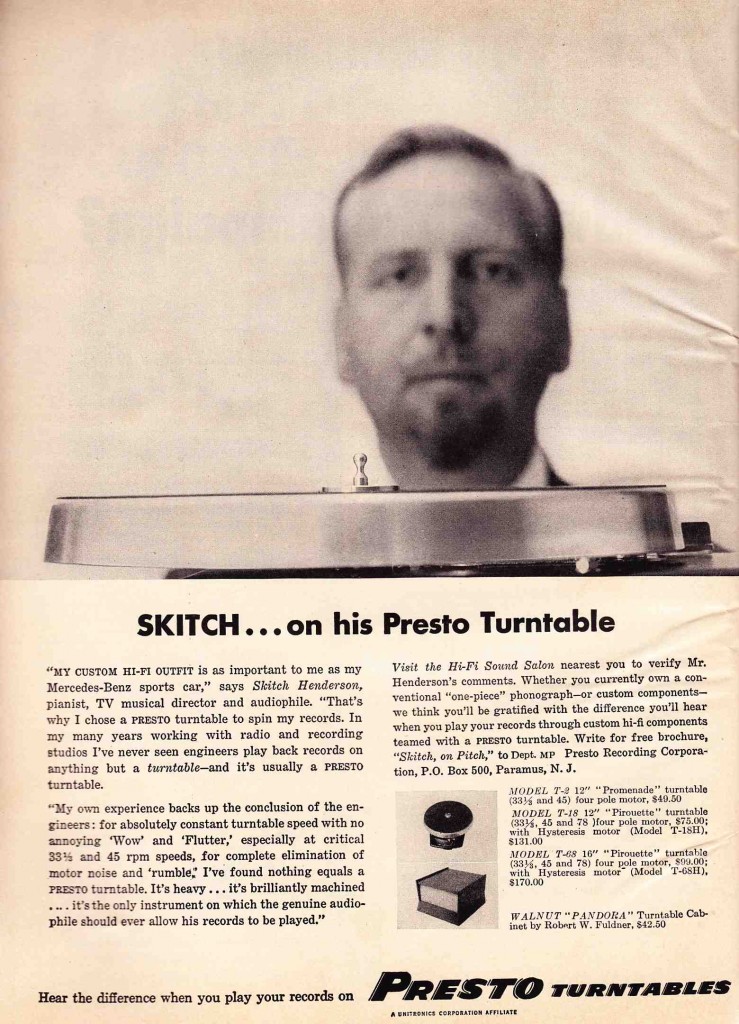
1957: A Few Bits From The End Of The Mono Age

From some 1957 issues of “Radio and TV News,” an electronic-serviceman’s publication, comes this collection of American Hif-Fi home audio kit of the era.  Notice the fact that…  it’s all mono. Commercial recordings released on stereo magnetic tapes were available as early as 1954, but it was the release of the first -ever stereo LP record in November 1957 forever turned the tide towards two-channel ‘Stereo’ recordings as the norm for recorded musical performances/productions.

Heathkit!  I have one of these A7s and damn it is a good-sounding little amp.  Anyone have a spare they wanna sell me (for stereo…. naturally…)?

I tend to think of Newcomb as more of an industrial-sound/PA sound company, but it looks like they made some home units too.  I have one of those huge glass-covered KX25 PA heads as shown here; it’s always been a little flakey but I can’t bring myself to part with it cos it came from a Catholic church and the knobs are labeled “Pulpit,” “Choir,” and “Sacrament Table.”  Take that, Kick/Ld Vox/ Bckng Vox.

Dude went to prison in 1974 for lying about the value of a music-collection that he donated to a university.  Tried to get Mancini and Bernstein to back him up and they would not.  Life is long….

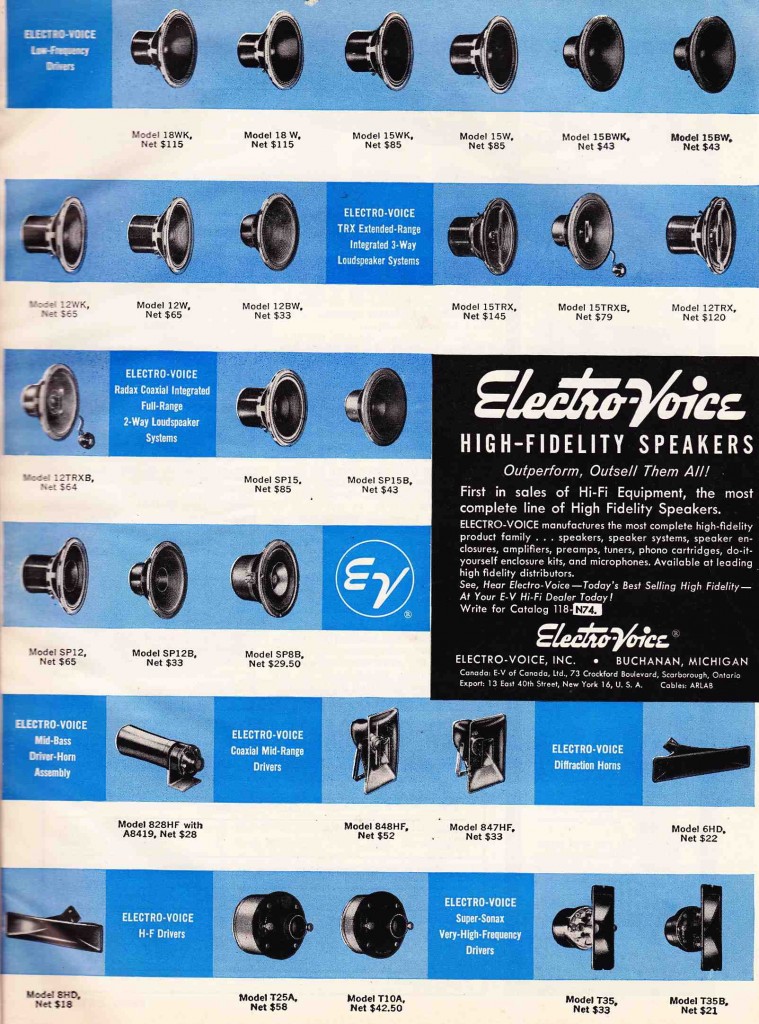
Electro-voice home hi-fi drivers c. 1957

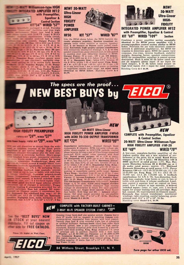
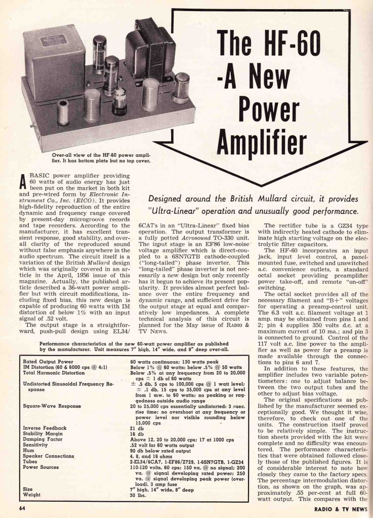
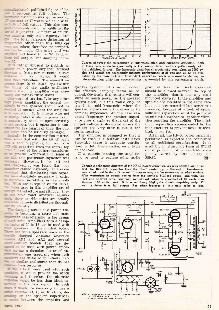
Eico home hi-fi amps and pre-amps circa 1957.  Eico was essentially the ‘other’ Heath(kit).  Eicos could be purchased either wired or as kits.  Here’s a two-page article on their flagship HF60, a beautiful amp with EL34 output tubes and an ultralinear Acrosound output transformer.

Categories
Custom Fabrication Technical

Marantz 7 RIAA Phonograph Preamp

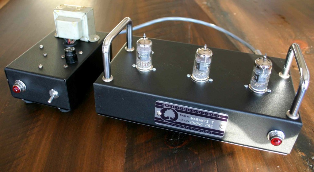
For my non-technical readers: a phono preamp is a device which does two basic things:  1) it equalizes the program that the phono cartridge picks up off the LP record, basically by boosting the low-end and cutting the high end, with this action centered at the fixed frequency of 1K hz (for full details on the ‘RIAA compensation curve’, and why it is necessary in the manufacture of LP records, read here); 2) secondly, a phono preamp must amplify the signal of the phono cartridge to roughly line-level (IE., the level that would come out of a CD player or VCR) and also deliver this signal at a low enough impedance such that it can be in-put to any receiver or consumer amplifier that it might encounter. Here is my attempt at a self-contained version of the phono pre-amp section from the Marantz 7 hi-fi preamlifier.
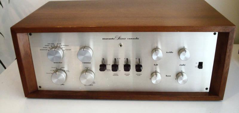
(web source)

I’ve never heard an actual Marantz 7c in action.  Considering that this dude, who does not seem like a total flake (based on his sales record) is selling one for $4,999 on eBay, I had to assume that it sounds fine (at least).   Marantz is one of the legendary American Hi-Fi brands from the ‘Golden age of Hi-fi,’;  their original line-up of products (before Saul Marantz sold the company) are widely lauded for both their sonic and aesthetic traits (see here for previous Marantz coverage on PS dot com).
(web source)

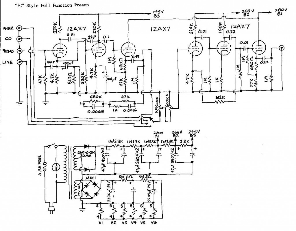
Above, the schematic that I used for this build.  It is a simplified version of the Marantz 7C, omitting such features as pre-RIAA disc compensation curves and bass/treble controls (for the complete 7C schematic, see here). The only change that I made to the audio section is that I added a 1K resistor between the signal output (the .47 cap) and the output jack.  Couldn’t hurt, right?  The phono pre-amp section consists of the three triode stages that you see at the left.  The three stages to the right are additional make-up gain that follow the overall balance and volume controls.  Important to note:  the output of the phono stage is a cathode follower.  This means that the signal is derived from the cathode of the tube rather than the plate.  This results in very little voltage gain (in that particular stage) but…  also…  pretty low impedance.  Which is what I wanted.
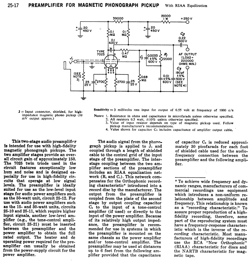
Above, the RCA RIAA phono preamp as published in several of their “Receiving Tube Manuals.”  I have built this RCA circuit before; while excellent-sounding, it does require an additional stage of amplification (I used a cathode follower circuit) to lower the output impedance of the device if you want to be sure it will ‘play-nice’ with all yr other kit..  Notice the note at the output leg of the circuit: “220000 ohms minimum.”  Wow!  That is very high impedance.  The only devices that this thing should feed are either the grid of another tube or possible a FET.  This condition makes the RCA circuit (on its own) insufficient as a stand-alone device.  And RCA did not really intend this to BE a stnd alone device; rather, they intended that you would build this into an amplifier where the circuit could directly feed the input grid of a preamp tube.  The Marantz 7c circuit, with it’s third cathode-follower stage, does not have this limitation.
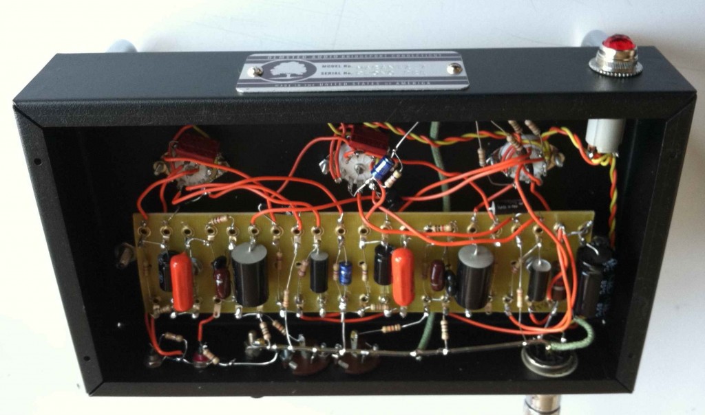
Above, the interior of the completed piece (audio chassis).  Note the French SOLEN coupling caps (my favorite due to good performance, reliability, and small size) and single ground buss (the piece of copper that runs along the lower edge).  RCA used the single ground buss technique in most of their broadcast equipment, and AFAIK, this grounding style cannot be beat for performance and ease of manufacture.
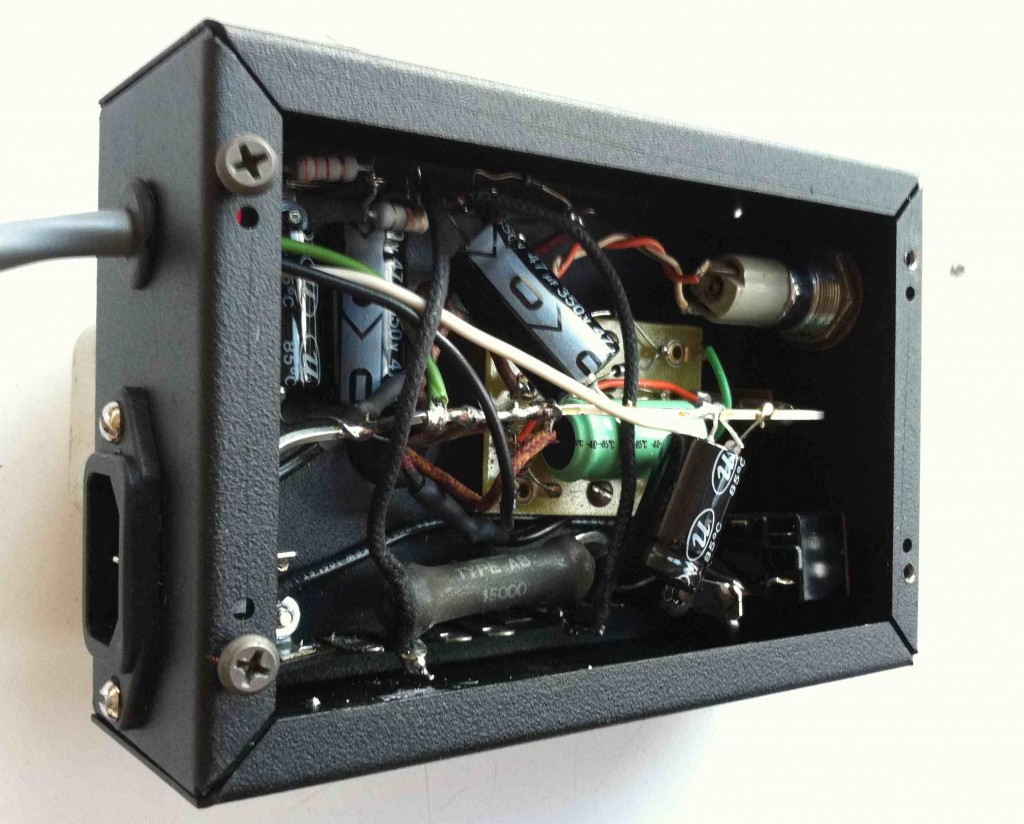
Above, the interior of the power supply.  I built the unit into two seperate chassis: audio and power supply: this was an aesthetic preference of the customer, and it also makes good sense when you are dealing with the miniscule audio voltage that emanate from a phono cartridge.  Sure enough, the finished piece exhibits no (z-e-r-o) hum whatsoever. I did not follow the Marantz 7C schematic for the power supply; I just built what I though was neccessary: a DC supply for the filaments and a B+ chain with 4 stages of filtering (no choke).  I used an NOS RCA power transformer that was a lil’ bit too exuberant for the 280V B+ requirement, hence the large-ish 15k ohm resistor near the bottom (the Marantz 7c schematic called for a 3.9k ohm in this position).  When all was said and done, after experimenting with a three different resistors in this position, I was within 1% of the voltages specified in the schematic.

So how does it sound?  Very good.  Compared to the RCA phono pre, it rejects WAY more RF;  it is very rich, extremely quiet, and the low-end response is so, so much better than the phono pre amps that come built into modern stereo receivers.  I QC’d the piece with a good cartridge and a clean pressing of TUSK and it was “as  Lindsey Buckingham intended it to be heard.”  If you are thinking about making a tube phono preamp, give this one a try; build cost is very low and it went together very fast with no hassle.

Categories
Technical

A Few Interesting DIY Audio Projects c. 1955

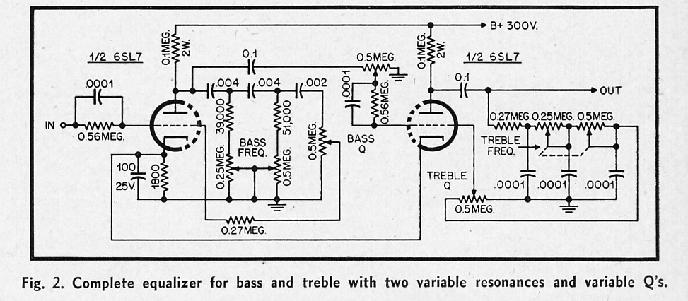
Circuit for a simple bass/treble parametric equalizer that uses no inductors.  Could be  a useful piece.  Not sure if 250k/500k dual pots are still available?  Since I have still not finished building the last tube EQ project that I described, so I’m not likely to craft this thing anytime soon.  If anyone out there picks this up and builds one, LMK…

Going back to AUDIO magazine in the early 50s: a few circuits that caught my eye. As always, if any of y’all out there build any of these, drop us a line and let us know how it went.
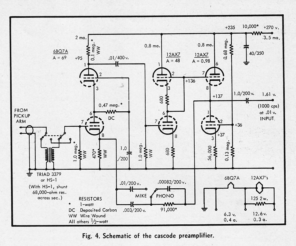
A ‘cascode’ preamp which features very high gain and defeatable compensation for phono cartridge.  I am not aware of any available mic preamp that uses this circuit.  a lot of gain available here…

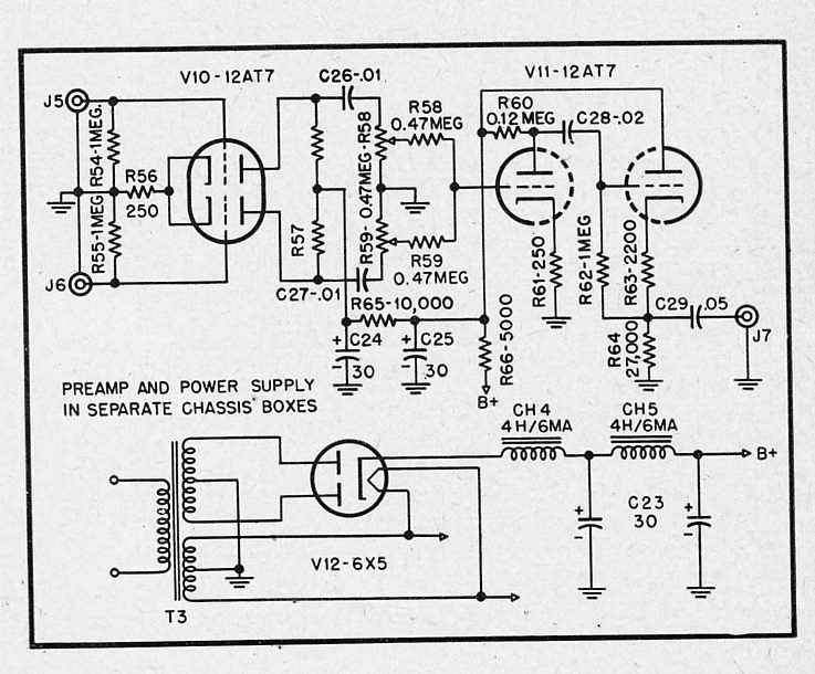
A low-gain preamp that mixes two high-impedance signals to a medium-impedance output.  Add a few transformers (500: 50K inputs, 15k:600 output) and this could be a useful tool for selecting/blending two mic signals to one track of (tape).  IE put a couple of mics on a gtr amp, blend to taste… I generally do this using submasters (busses) on the console but here’s a potential way to do it that uses a much simpler signal path, IE right from the mics into the convertor (or tape machine).

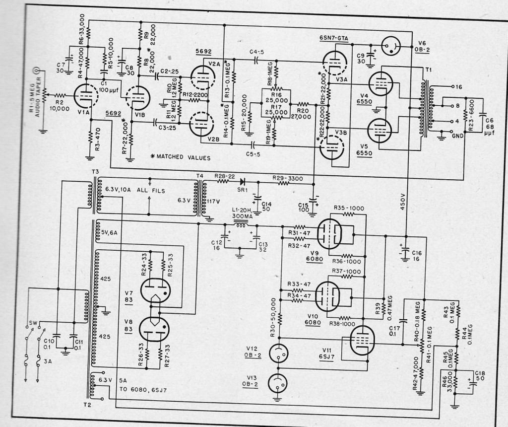
A 50-watt ultralinear power amp using 6550 power tubes

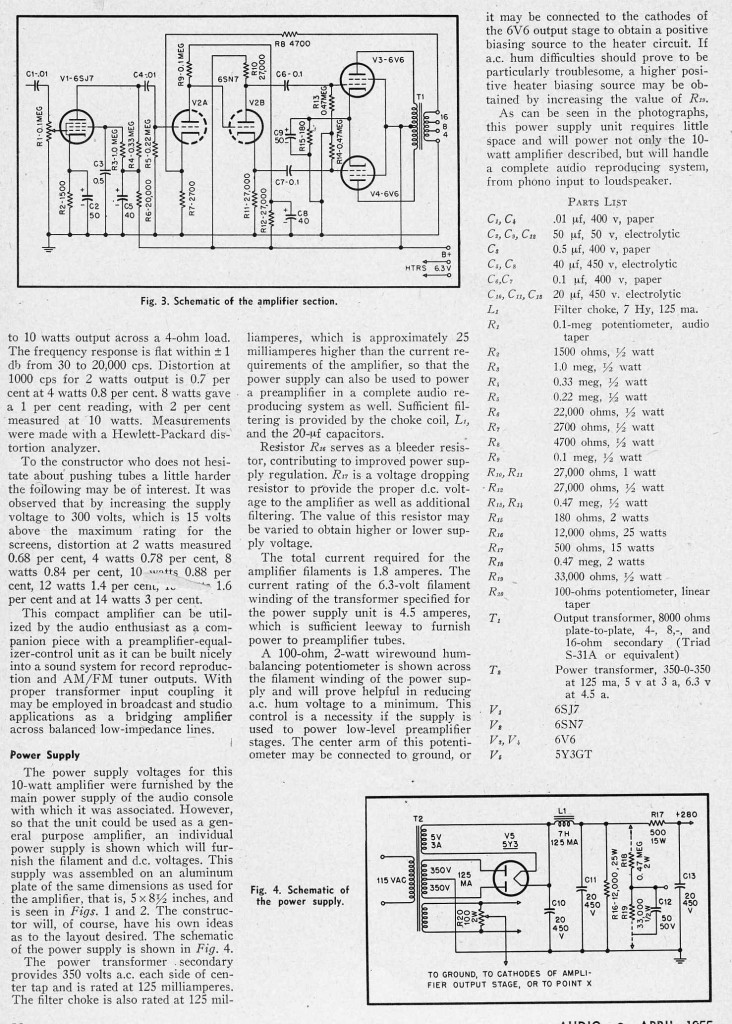
A 12-watt 6V6 power amp with some negative feedback and a pentode input stage.

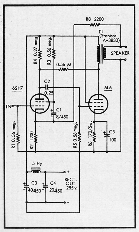
A simple 8-watt power amp that uses a 6SH7 input tube and a single 6L6 output.  This circuit uses a great deal of negative feedback in order to supposedly get more linear response with cheap output transformers.  I’ve never used the 6SH7 tube before…  curious though.

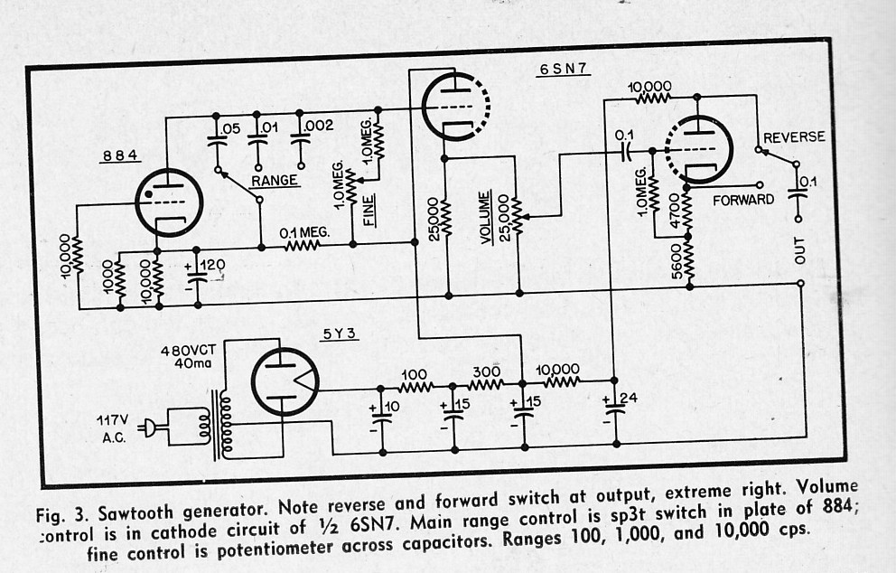
A simple design for a variable sawtooth wave generator.


Categories
Technical

Audio Engineering Magazine Pt 4: Schematics

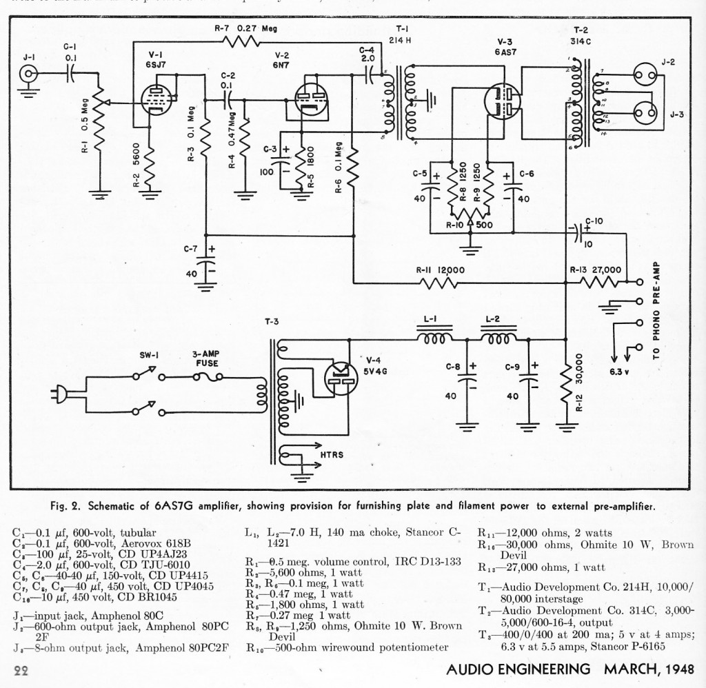
Today we’ll look at some of the more interesting audio-circuit plans and schematics from the first two years of Audio Engineering magazine.  Pictured above is a great lil’ amplifer (approx. 30watts) that uses a single 6AS7G tube for push-pull output. I’ve never used these tubes, but they are real cheap.  Apparently they are sorta like 2 2A3 triodes in one envelope.  Except that they cost $13, rather than $200 for a vintage 2A3.

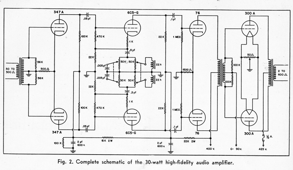
A fully-balanced 30-watt amp using about a million dollars in tubes.

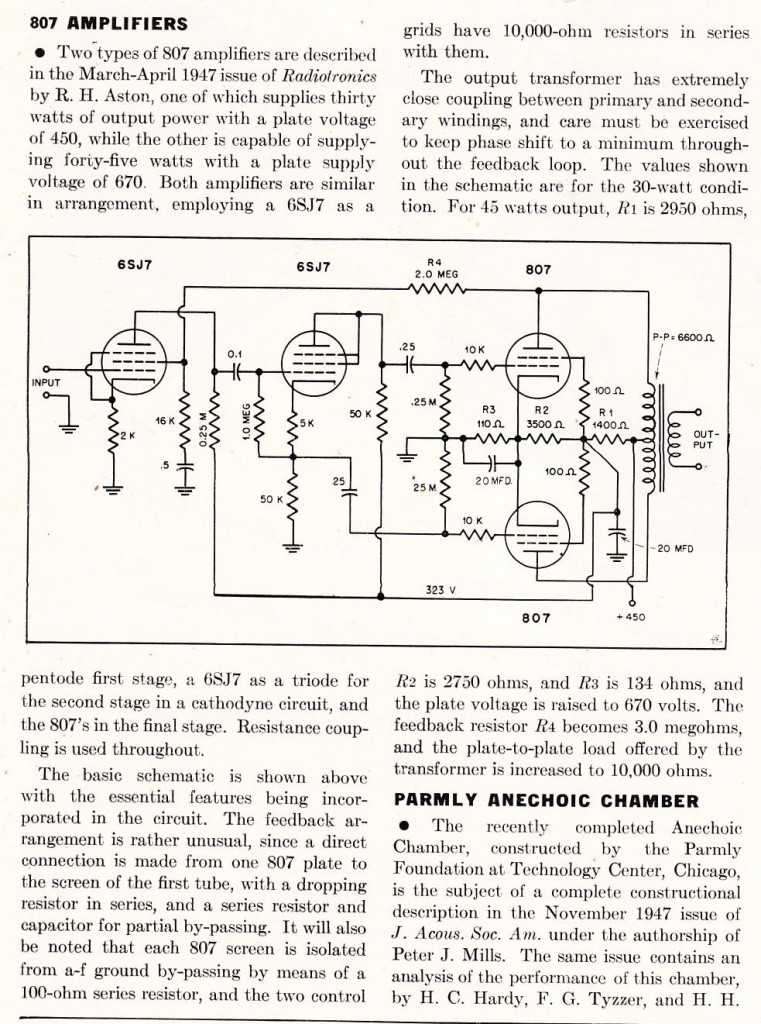
another 30-watt amp, this time using the very cheap 807 tubes.  The 807 is similar to a 6L6, except that the grid connection is on a top cap.  807s can also handle crazy high voltage.a

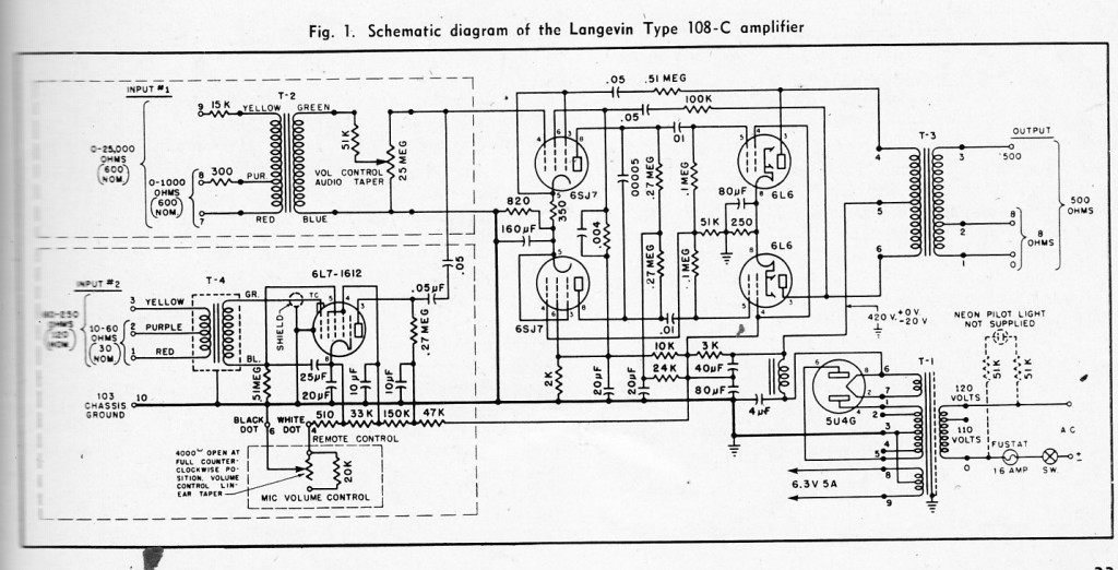
A schematic for the venerable Langevin 108C, which was apparently a very popular choice for industrial audio distribution in the ’40s.

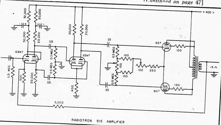
Another 807-based amp; this one is an RCA Radiotron model 515.  This looks like a great circuit.  Wish I had kept those 807s i found last year…