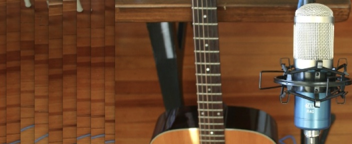
 I continue to get a lot of readers here drawn to my earlier post on the MXL R40 ribbon mic. Click here to read that earlier post. In that article I describe replacing the stock transformer with an inexpensive Edcor unit and getting very good results. Anyhow, shortly after i wrote that piece, the price of the MXL R40 shot up dramatically – to around $120. Well I guess they couldn’t move ’em, cos they are back for $69.99. A great deal IMO. Click here to pick one up.
Month: November 2012
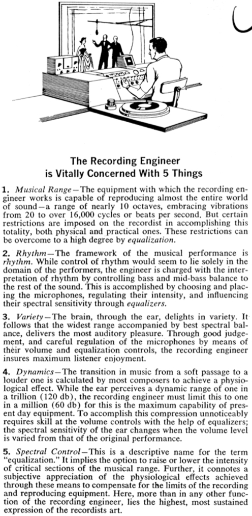
1961: Five Things
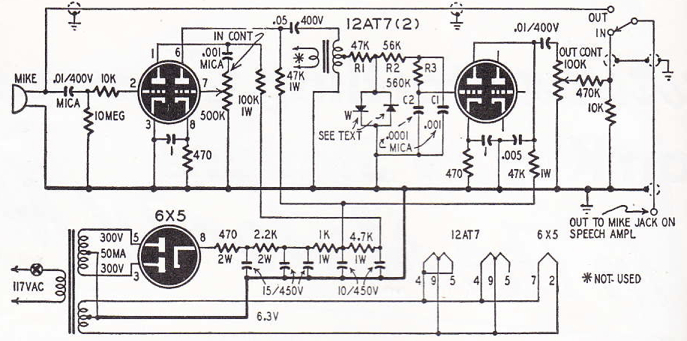 Download a short piece from RADIO-ELECTRONICS, 1950, on the subject of a DIY audio-compressor:
DOWNLOAD: DiodeCompressor1950
 This promises to be an interesting unit. It’s designed (like a Shure Level-Loc) for Mic-Level-In, Mic-Level-Out, but that could pretty easily be changed for balanced-line operation by omitting the first 12AT7 stage and using a modest step-up transformer (maybe 1:3 or 1:5) going into the input level pot, and then adding another output stage and output transformer. (Since 1/2 of the 2nd AT7 is unused, I am thinking: eliminate one of the 12AT7s entirely, build this circuit minus the first stage using one 12AT7, and then add the output stage from the Altec 1566). The unit promises to add distortion, and there is some sort of low-pass network before the 3rd grid that will also need some sort of variable components added in order to control the quality of that distortion. My biggest question, though: will plain ‘ole IN4007 Diodes work in the circuit? I plan to build this thing soon and all questions will be answered… always looking for new (old) sources of novel grit+crunch….
DIY Remote Broadcast Mic Preamp c. 1950
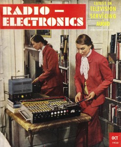
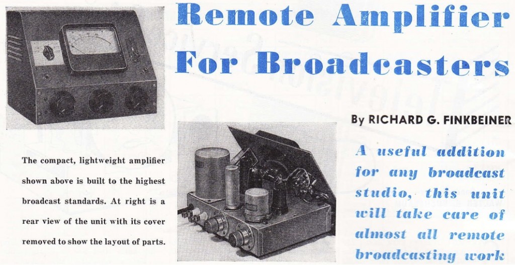 Download a four-page piece from RADIO ELECTRONICS, March 1950, on the subject of Build Your Own Two-Channel Remote Amp. Author is Richard Finkbeiner.
DOWNLOAD: RemotePreAmp1950
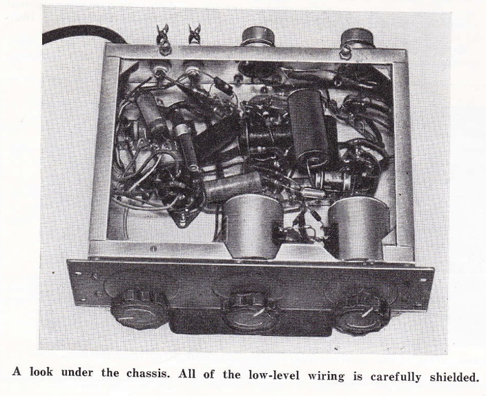 Again with those T-pads. Anyhow, we have here two 6J7 pentode stages in series supplying a 6F6 (v v similar to a 6V6) output stage. Here’s the schematic:
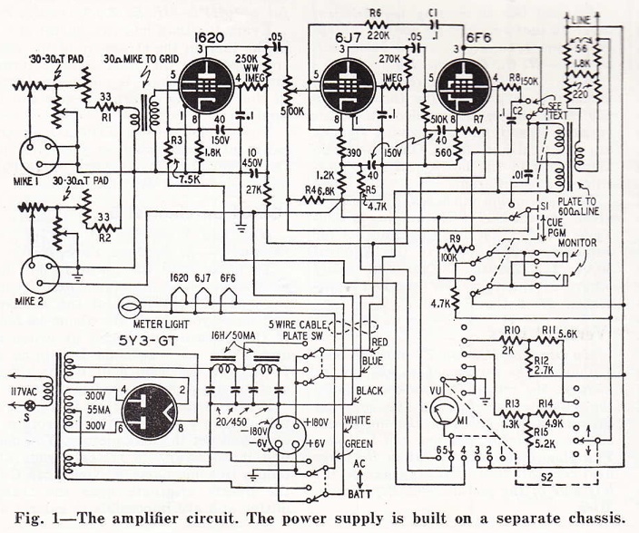
 The schematic is a bit opaque due to the fact that this piece is designed, ‘at the touch of switch,’ to become a cue amp – to receive signal, via its Station-Link, rather than send signal. Confused? The article will make it clear. Anyhow, if anyone has tons of time on their hands, it might be interesting to re-draw this schematic minus all of that circuitry. I would be v curious to know exactly which output transformer the designer used: a 5K to 600 ohm transformer that can handle 3 watts of DC and remains flat 30hz – 15khz? Sign me up. (It sure looks like a Langevin, but as I don’t have the early 50s Langevin catalogs, I can’t say which model it might be) I can tell you that even the modern Lundahl that I use in my BRDCTR can’t offer quite that level of performance, although Lundahl does promise it…
Also of note to all you builders out there: the author observed a full 15 db less overall noise with a 1620 in the input position relative to a 6J7 in same. I wonder for how much longer we’ll be able to easily buy NOS 1620s…
Fill In The Blanks
Audio Mixing Console Circa 1949
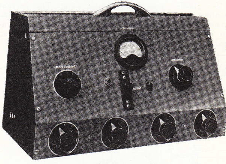 Download a three-page article from RADIO ELECTRONICS, Feb 1949, on the subject of Build Your Own Audio Control Console. Author is Richard Dorf.
DOWNLOAD: AudioConsole1949
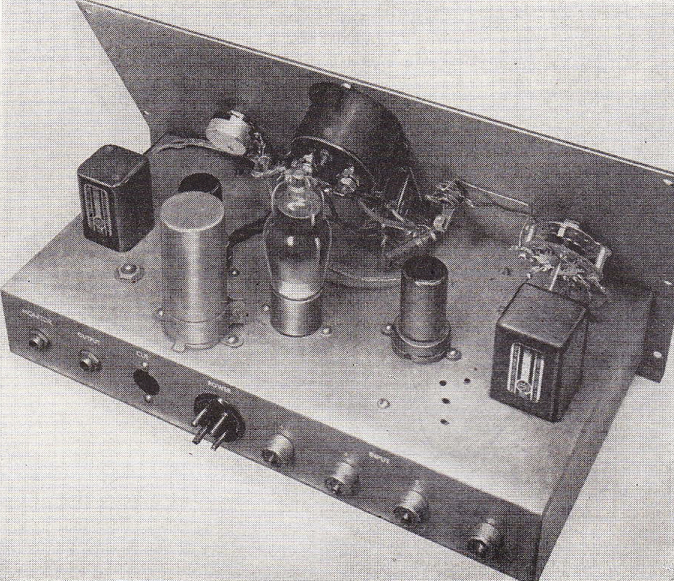
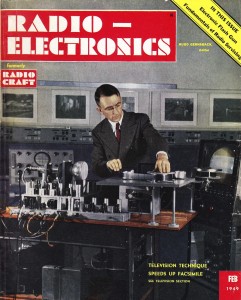 Kinda a wacky design: it’s intended for mixing four low-z unbalanced sources, using multiple T-pads summing through a resistor network to a single tube grid (rather than using multiple input transformers and multiple tubes). Not really so practical. I’m posting this primarily in the hope that one of my readers can elucidate the output stage design for me. It seems like it must be an error, but maybe not?
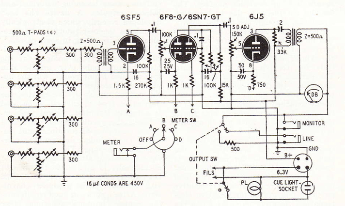 The article states that ‘any plate to line output transformer can be used,’ which means that the design does not specify an air-gapped (DC-handling) transformer. Not sure how that applies to this design. Seems like the DC would be quite different on either side of that 33k resistor? Also not sure how any signal would develop there? Is it possible because on of the secondary legs is terminated to ground? Confused. Were there any commercially-manufactured pro-audio units that used this kind of line output stage?

