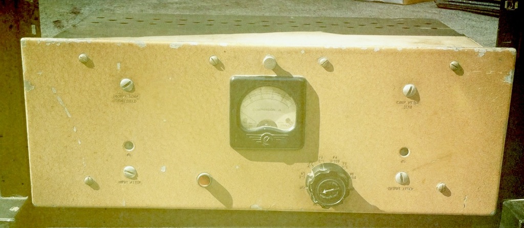
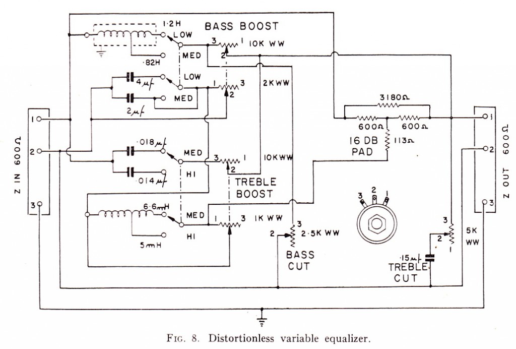
 Above, a ‘distortionless’ equalizer circuit circa 1961 as designed by one Carlos Moura. Separate bass and treble boost functions (2 frequencies each) and bass and treble loss cut. I do not know the range, frequencies, or insertion loss. Can anyone tell me if/when this was manufactured, and by whom?
Category: Technical
Many of my regular readers will be familiar with the Shure Level-Loc. For those unfamiliar, the basics: the Level-Loc is a brickwall limiter made by the Shure microphone company for public-address-system use (podium mics, specifically) in the 1960s. It uses discrete transistors and transformers in the signal path; it offers balanced mic-level i/o and an unbalanced consumer-level 10K ohm impedance output as well. There is an input-level control (simply a pot that follows that secondary of the input transformer) and a switch marked ‘distance selector,’ which seems to me to be a threshold control. That’s it for control. It is fairly noisy (full-bandwidth noise), even after a recap, and the transformers are not especially well-shielded. It runs off of a 9V battery. For more information on the Level-Loc, you might want to start here.
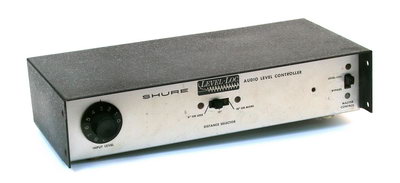 Anyhow…seems like a toy/piece-of-junk and maybe it is, but these things have become highly coveted for use in recording rock drum performances. How much so? Well, how many other prosumer PA-system pieces are currently available as a plug-in, an API-500 series module, and a boutique re-build? (image source for above)
I recently picked up a clean Shure Level-Loc for a few dollars at a yard sale; after the aforementioned re-cap (and we’re talking about 20 capacitors here…), it was sounding like it was probably operating within its original design parameters. I was intrigued, and figured it might be worth getting it into the racks at Gold Coast Recorders to see what it could do. GCR is a big, live-sounding room, so there’s plenty of sound to get out of it with a squashed compressor. The only potential problem: the Level-Loc offers only mic-level or low-level medium-impedance output. I like to run my mic preamps directly into the Lynx convertors; so for the most direct signal, I would need a bridging amp to bring up the level and lower the impedance of the Level-Loc. It would be nice to have an output level control too, and I wanted the piece to be as physically small as possible so that it could sit directly next to the Level-Loc on a 2RU rack shelf. Here’s what I did to solve all of these problems and fold the Level Loc into the studio alongside all the other outboard mic preamps.
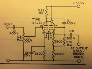 ***********************************************
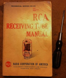
Most of the RCA Receiving Tube manuals have a schematic for some sort of ‘audio input amplifier’; I wanted one that would provide about 20db of gain as well as a very low-impedance output so that I could drive a 15K:600 output transformer easily (I used an NOS UTC Ouncer to save space). Based on this i selected the circuit above RCA manual # RC-24. One 12AU7 tube. Simple, easy. The physically smallest plate/filament transformer that I had on hand was an NOS Stancor 120v:120V/6.3V, so I used the voltage-doubler B+ supply circuit as-found in the Altec 1566 and 438: here is that schematic via Tangible Technology:
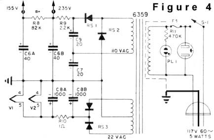 For once i actually did not bother wiring up a DC filament supply, since the gain of the unit is pretty low. This was the right choice, as i can hear no hum at all in the finished unit. I added a 500K pot at the input jack and voila. The whole thing fit inside one of those aluminum Bud Boxes that some folks use for DIY’ing guitar effects pedals. I left the power transformer bolted outside the unit on the rear; it’s always a good idea to keep power transformers away from audio transformers if you can. Here’s the interior of the unit:
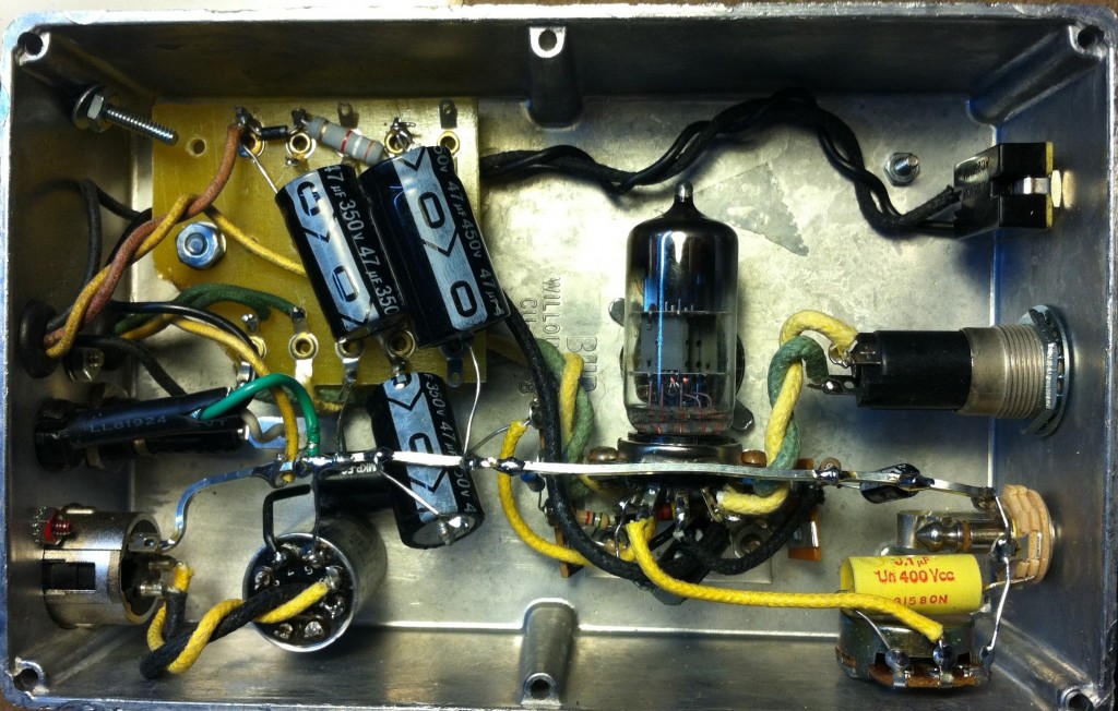 …and below you can see the finished piece. Not my finest piece of industrial design but it does the job. I put the 1/4″ TS input on the front of the unit so that I can use it as a DI input for Keyboards ETC if the need arises. The circular grill on the top surface of the piece is a heat-vent positioned directly above the 12AU7 tube.
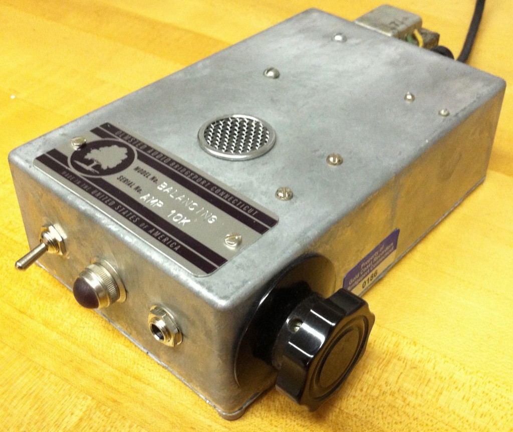 The unit performs well, especially considering that there are only two stages of filtering in the power supply. I always use four stages of filtering in the equipment that I build for customers, with at least one choke; I was curious this time to see how the basic Altec B+ scheme worked, though, and it seems just fine! People love their 1566s and 438s so fukk it. Good enough is sometimes good enough…
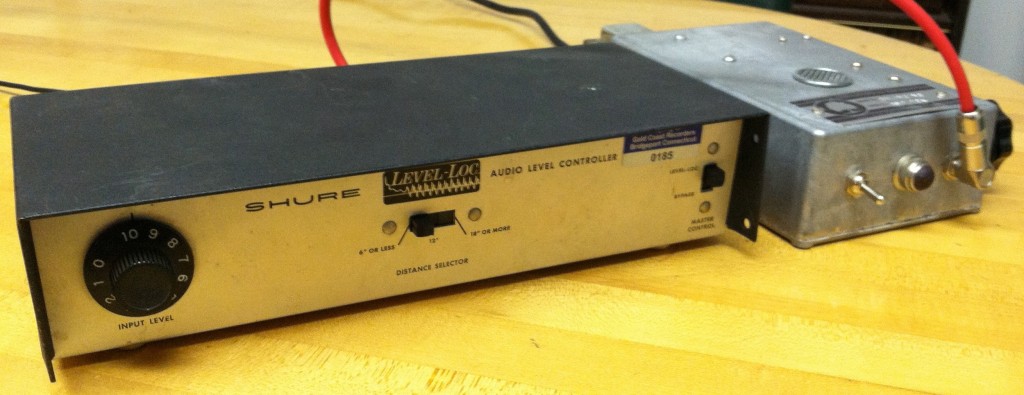 Above, the two units side-by side. So how does it sound? TW and I were putting down live drums on a track at GCR and here’s the result we got.
First, the drumbeat: close-mics only: CloseOnly
Here’s the same mix, but with the Level Loc signal added: in this case, the Level Loc was amplifying a figure-8 ribbon mic 20 feet from the kit, with the null of the mic facing the kit; the waveform was then re-aligned to eliminate some of the delay: withLevelLoc
And finally, the Level-loc signal only: LevelLocOnly
The Level-Loc is aptly named. Regardless of what you put in – a baby’s breath or an atomic blast – you get the saaaaame level out. Zero dynamics. It’s pretty uncanny. And a great sound for heavy rock drum beats. This is the 2nd track that I have used it on in a week and I think it will continue to get a lot of use at the studio. The output of the balancing amp is a little low – even with the input attenuator all the way open it cannot quite get to full level via the Lynx convertors. It’s good enough, but it could stand to put out a few more DB. If you build one of these devices for use with your Level-loc you might consider using a 15K:60K interstage transformer at the input to get a little bit more level out of it; or re-bias the two stages in order to use a 12AT7 instead of the 12AU7.
 Above: Belden 8411, 8422, and 8412 microphone cable. I still use Belden 9451 for most studio hard-wiring tasks, although I have to admit that I am very devoted to Canare StarQuad for actual mic cables. Anyone out there prefer Belden mic cable to the Canare?
Above: The Altec 680A omni dynamic. This one looks very strange. I am very curious to know what it sounds like. Anyone?
 The Altec M20 condensor microphone. These seem to still be is use in studios. I hope I turn up one of them soon… folks seem to like them a lot.
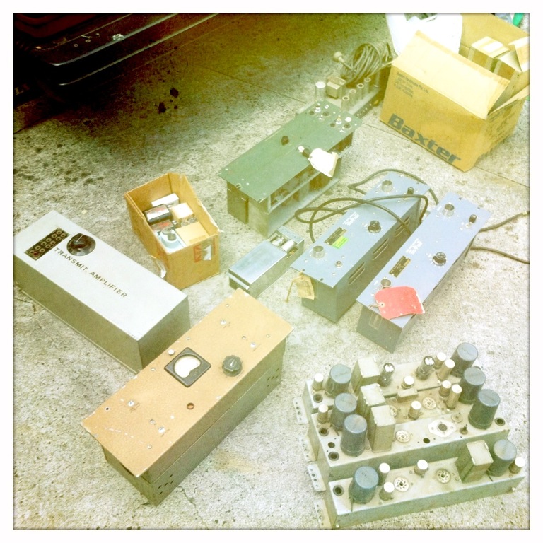 Download a 24pp pdf with schematics and technical information regarding all AWA-brand vacuum-tube broadcast audio amplifiers circa 1967:
DOWNLOAD: ABCstudioEquipment
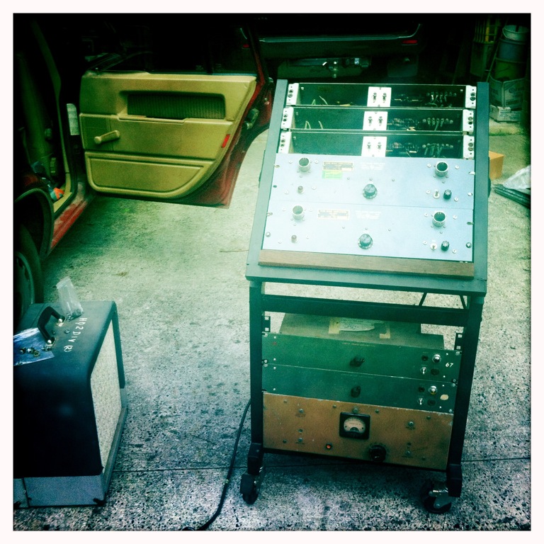 Big thanks to PS dot com reader E. Lorden. E. lives in Australia and has provided us with extensive schematics and technical data on AWA broadcast-audio equipment. AWA was the ‘RCA’ of Australia throughout much of the 20th century: they made and marketed both consumer and professional electronics equipment as well as engaging in actual broadcasting. Due to a very protective import-taxation scheme in place in Australia until the early 1970s (as well as the high cost of shipping imported goods to that country), AWA was highly incentivized to develop its own unique line of broadcast audio equipment for the Australian market. I have personally never seen any of these items myself, and many of the circuits are different than any US broadcast audio components that I am aware of; perhaps there is more of a Telefunken heritage to this kit. Or perhaps it’s genuinely just unique. Anyhow, plenty to dig into… limiters, mic preamps, power amps, etc… Although the document is dated 1967, the circuits covered extend well back to the 1940s, judging by the types of ‘valves’ employed.
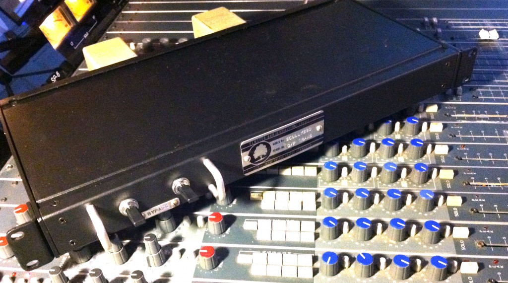 Sometime in the past couple of years, Tape Op ran a short piece by Allen Farmelo titled “Using Transformers to Transform Audio.” (EDITOR: the original Farmelo article is no longer available as far as we can determine – link removed) My reaction at the time was ‘it’s about time!’ Audio transformers are a crucial part of what we think of as an ‘old-school’ or ‘vintage’ sound. My clients at the studio often ask me what makes tube-audio gear desirable, or ‘better,’ and I am always quick to relate that when vacuum tubes are operating in a linear (IE., not-distorting) way, you shouldn’t really ‘hear’ the tube – it should be amplifying, nothing more, nothing less. Of course once you push a tube into breakup the effect can be quite different than a distorted FET or transistor but you get the idea. A clean tube signal should sound… clean! So, anyhow, the next point that I will make is that tubes are rarely very far from audio transformers, at least in pro-audio equipment, owing to the usefulness of ‘free-gain’ at input stages and the necessity of plate-or-cathode-matching at output stages (if this sounds like jargon to you/// basically/// tubes need transformers in order to play-nice with other pieces of gear). The point: what we think of as ‘that tube equipment sound’ is really due to the transformers as much as the tubes themselves.
I won’t go into all the various effects that transformers create, as Farmelo does a very good job of explaining it in his piece. Suffice to say: it is a very real, and very subtle effect. Audio is a game of inches, though, ain’t it. So when a regular customer of mine recently ordered a custom piece to allow him to use some high-quality transformers as a subtle signal processor in his studio, I was ready to go. Here’s what I whipped up:
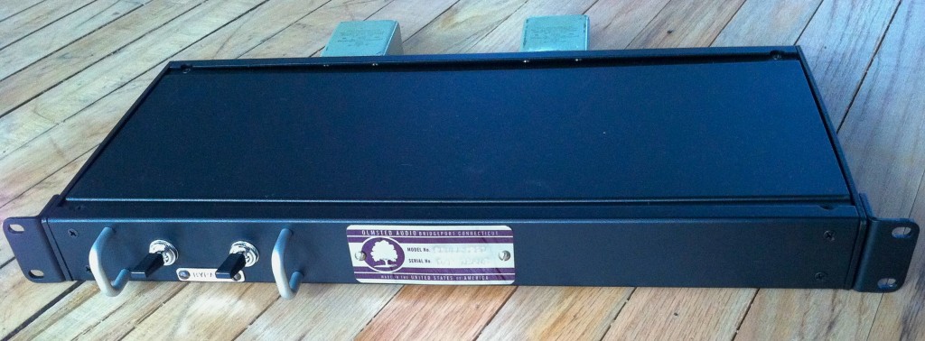 A single-rackspace unit – two 4PDT toggle switches on the front offer clickless true-bypass for each channel. The switches are beautiful Japanese made units; each can handle 12,000 (yes twelve thousand) watts of electricity. They should last…
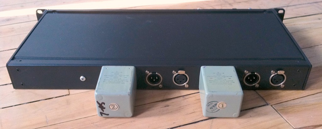 On the rear we see Neutrik XLRs (my price/performance favorite) and… a pair of 600:600 FREED output transformers pulled from some Scully 280 electronics that were too far gone to rebuild. The transformers themselves are flawless, though, and they sound great; I have many of them at use in my own studio for various tasks.
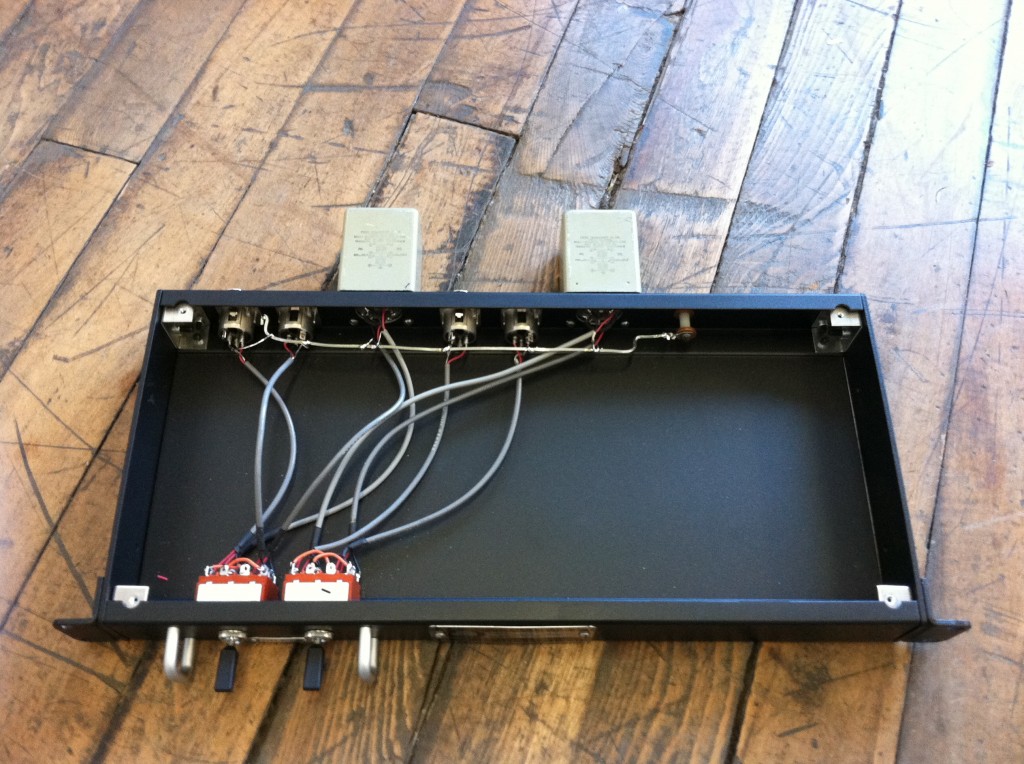 Inside it’s just a buncha wire… Belden 9451… and at the rear you can see the heavy copper ground buss with a single chassis-contact point on the left.
Overall the transformers introduce a 1db loss in level to the program. The effect is certainly subtle at reasonable levels, but I notice a more ‘organized’ sound to the extreme low end – it seems less vague while still retaining the full extension in the subwoofer.
 PS dot com reader Paul R. was kind enough to send us a scan of “Audio Anthology,” (ed. C.G. McProud) a 124pp softcover published in 1950. “Audio Anthology” (hf. ‘AA’) is a collection of project-construction articles aimed at hi-fi (rather than pro audio) enthusiasts. All of the material had been previously published in Audio Engineering magazine during its first four years of publication (1947 -1950). See here, here, here, here, here, and here for previous 1940’s AUDIO ENGINEERING MAGAZINE coverage on PreservationSound.
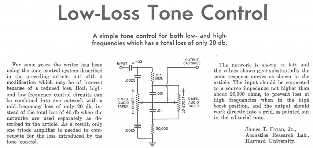 Above, an interesting boost-EQ stage that could be helpful in an instrument or mic amplifier. Can any of our helpful readers advise which caps or resistors in this circuit could be modified (and within what range) to alter the turnover frequency of the two filters at work here? I am guessing that the answer is: all four caps that follow the input DC blocking cap… which would basically get us back to this piece, which i swore i would never build again…
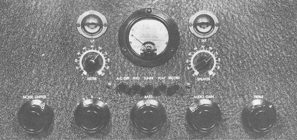 Above, the most complicated tube amp I have ever seen. Kinda feel like Shadow Hills Engineering must have come across this image at some point. Dynamic noise suppressor, phono pre, two eq controls, visual feedback of high and low frequency drive, variable metering, tons of input switching… talk about the kitchen sink. This project is organized around the very interesting 6AS7G dual-triode power amplifier tube: basically two 2A3s in one glass envelope with a 6V heater supply. This is potentially some useful information, especially when you consider that a 6As7G is only about $13 from AES (priced out 2A3s lately?). I think that there could be a unique new guitar amplifier in the works soon…
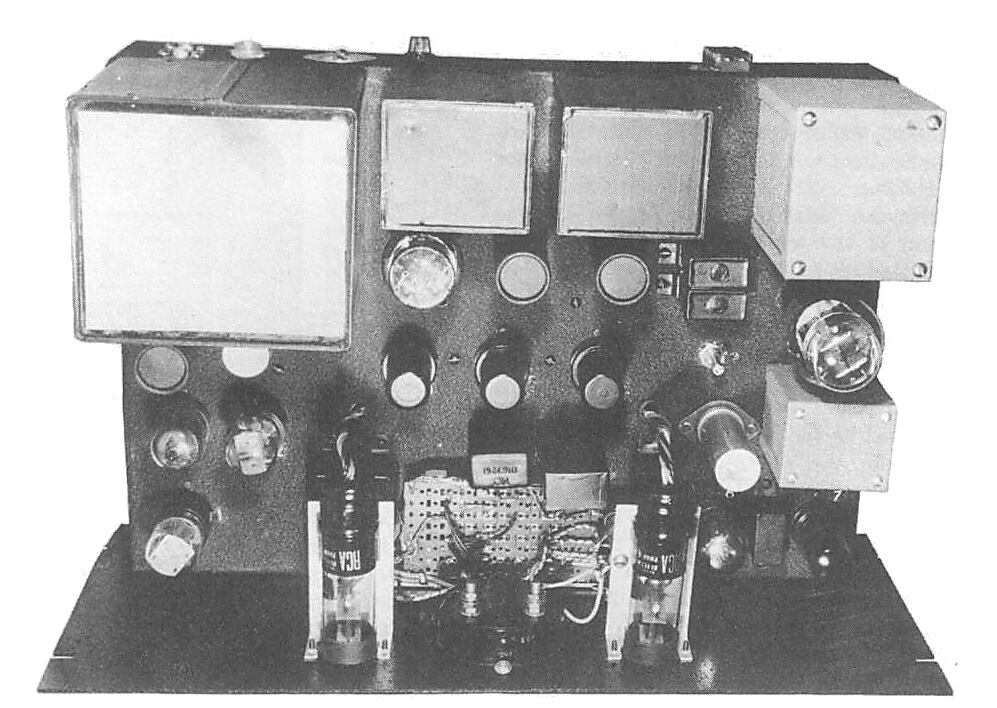 My lord. At least they didn’t try to thrown in an AM/FM tuner. Follow the link at the end of the this post for schematics and parts lists for some 6AS7G amplifiers.
‘Audio Anthology Vol 1’ is available at Amazon dot com.
FOLLOW THE LINK BELOW for 6AS7G project schematics…
NOTE: the above unit eventually did sell on eBay for $35,000. See below for scan…
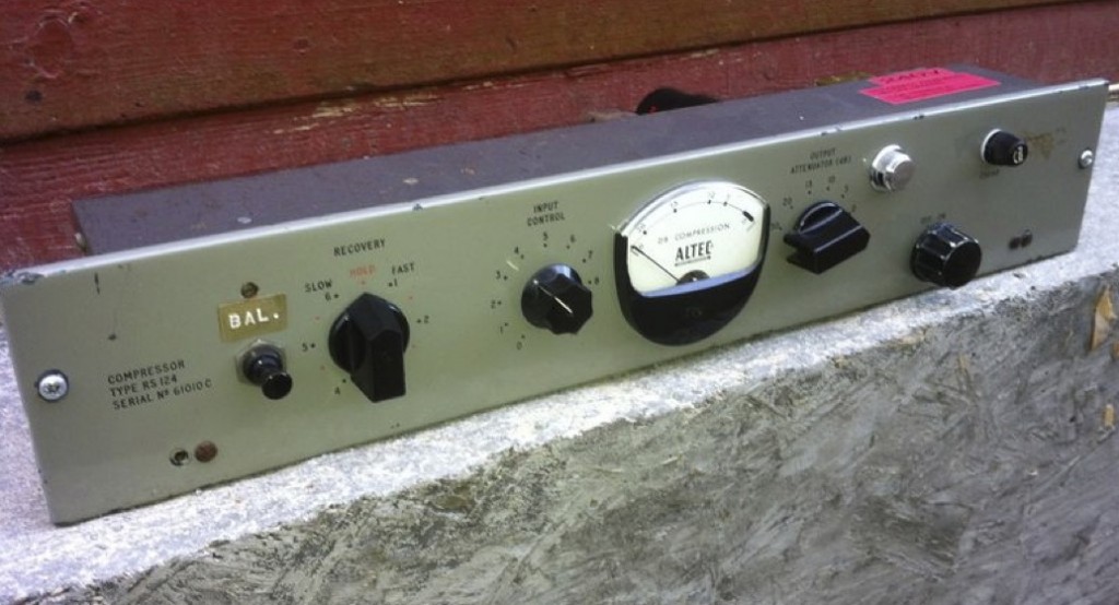
Here’s something that you don’t see everyday. Courtesy of this eBay auction, an apparently original EMI-modified Altec 436B. Buy it now for $55,000 (fifty-five-thousand) US dollars. If this price seems absurd (and it surely is optimistic at best), I will point out that the seller claims (and he/she may very well be correct) that this particular unit was in fact used on numerous Beatles recordings. The particular quality of its compression, pumping, and mild distortion were integral to creating the vocal and drum sounds of the most widely-heard and widely-copied pop/rock recorded sounds in the entire history of sound recording. Add to that likely provenance the fact that only a handful of these units were ever made and you have a very unique piece of audio history on the block.
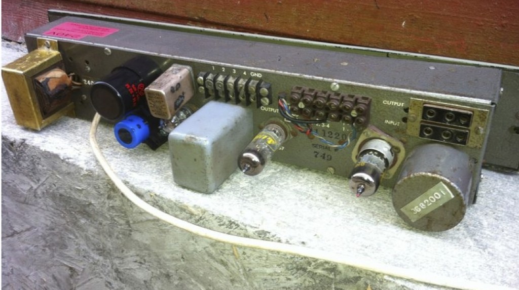
Here’s a shot of the rear of the unit. A few things worth noting: the JJ multicap (above the blue LCR cap) is of recent manufacture, indicating recent servicing. The lineup of three tubes and only two audio transformers indicates that this unit began its life as a 436(x) compressor, not a 438(x) mic pre/compressor. The mains transformer (far left) was necessarily replaced to facilitate easier use in a 220v country. My biggest question (and please, readers, fill me in… ) is: what is that unit above the 6AL5 tube? Is it a 2nd output transformer to allow of use of a T-pad attenuator on the output while retaining output balance (IE., the T-pad would go between the two transformers)?
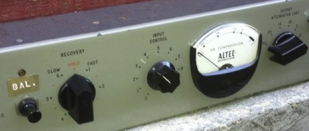
Getting back to the front panel, we see evidence of the modifications that EMI made in order to make the 436B more useful in the studio. From left to right: a ‘balance’ push-button switch (not sure what this is, but i image it might have something to do with balancing the vari-mu action of the two halves of the gain-reduction tube? not sure how a pushbutton switch would be implemented there?). Next, a ‘recovery’ or ‘release’ control (self explanatory), then factory ‘input’ attenuator control, and to the right of the meter an output attenuator.
Anyway…those of you who have been following PS dot com for a while will know that I have a tremendous interest in these Altec compressors; I have restored them, modified them, scratch-built them, and use one regularly in the studio. Here’s some links to catch up:
History of the Altec 43(x) compressor and its relation to the EMI RS 124
Adding a balanced output attenuator to an Altec compressor
Modifying an Altec 438a compressor to gain many of the EMI RS124 features
UPDATE: since this article seems to get an enormous number of pageviews, I thought I should mention that we did in fact carry-out the intended shoot-out of the mod’d R40 versus a range of other similar ribbons (with a Royer R121 as the ‘control’ sample. CLICK HERE to listen to some apples-to-apples action.
I love the sound of ribbon mics. Friends and clients will often ask me why, or ‘what’s the difference’ (b/w a ribbon and other forms of mics) and I generally reply that good ribbon mics seem, to my ears/brain, to reproduce sound in a way that more closely resembles the actual event. To my ears, a good condenser like my U87 or U47 FET sound fantastic – more spectacular than the actual sonic event, in many cases – and a good dynamic mic like a 441 or an SM7 can really improve the sound of an electric guitar speaker – but there are ways that they do seem distorted, especially on material with complex, aggressive high-frequency content, such as cymbals played with a heavy touch. Ribbon mics also seem to respond better to additive EQ, and on bass instruments they also seem to create the impression of bigger, fuller bass without actually taking up as many DBs in the mix as you might expect. Anyhow, I keep writing ‘seem’ because all of this is, necessarily, subjective. That being said, these are opinions that more and more recordists and musicians have come to share since ribbon mics came back into vogue a decade or so ago.
FOLLOW THE LINK BELOW TO READ-ON AND LEARN HOW TO MAKE YRSELF A REAL-NICE SOUNDING RIBBON MIC IN 45 MINUTES FOR UNDER $100…
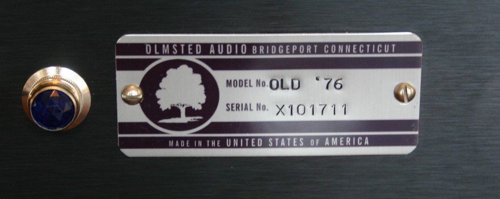
The Old ’76
 My latest microphone preamp design is completed and sounding very cool… The Old ’76.
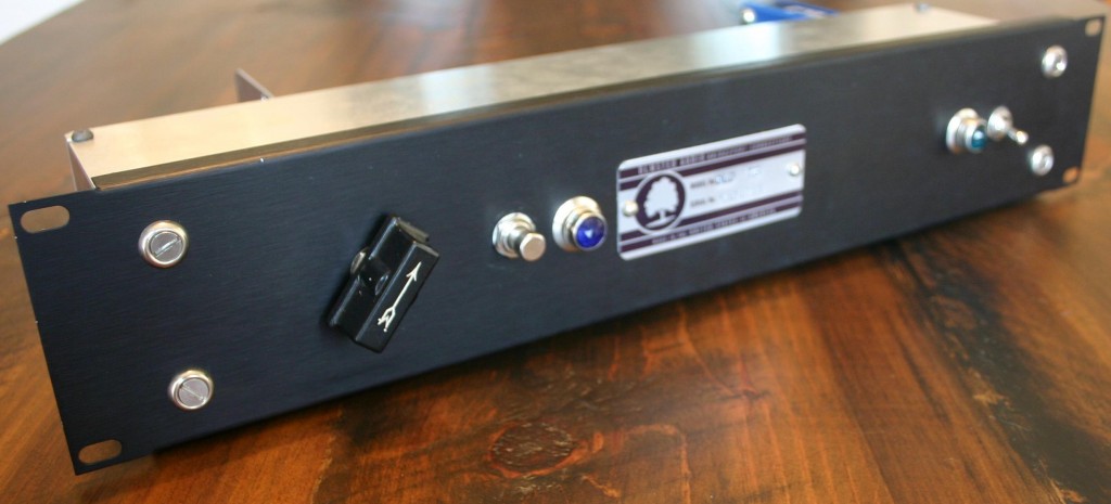 The Old ’76 is a novel three-stage design; it’s not based on any past or current production microphone preamp. That being said, the circuit is nothing revolutionary: an input transformer (in this case a UTC O-1, as I was temporarily out of Jensen 115s) connects to an RCA 76 tube, biased in textbook (or, at least, RCA-Receiving-Tube-Manual-book) fashion; volume pot follows and then on to a 6SL7 tube with the first stage plate directly coupled to the grid of triode 2; the output is a cathode follower with a Solen cap and onto an Edcor output transformer. The pushbutton switch (with associated pilot lamp) activates 48V phantom power. Overall gain is approx. 60db and response is flat 50hz – 18khz. I am betting that the slight high and low end roll off is due to the UTC O-1; the next build will use my customary Jensen input transformer and we should see 25hz-20khz flat response.
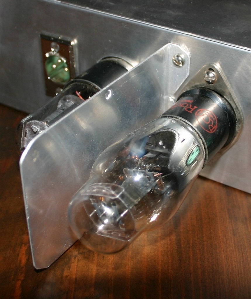 76 tubes were often used in ancient console radios with a large tubular shield positioned around them; the reason for this became quiet clear once I had finished my piece; before I added the above-depicted aluminum plate between the 76 and 6SL7, I was getting some unpleasant ringing on very high frequencies.
I had wanted to build a mic pre with some of these very old two-digit designation tubes for some time now. Hi-Fi fans seem to love the 76 tube, so I figured there was probably something worth investigating. 76 tubes are readily available and pretty inexpensive; it is a bit of a challenge to find the 5-pin bases that they require though. AES sells only one 5-pin base, and it’s expensive and oversized. My prototype unit here used an older Amphenol socket that I dug up somewhere.
 Some other miscellaneous design notes: B+ rectifier is a 6×5 tube; hammond 15mh choke was used in the B+ chain; DC filaments, as usual; the phantom power supply has a slow ramp-up when activated; the three-pole phantom switch 1)connects the 48v supply to the main power supply; 2)connects the phantom indicator lamp to the 6v supply; and 3) connects the 48v to 6.8k resistors that actually connect to the mic input jack. I find a three-pole switch necessary in these instances because there is some ‘drain’ time involved when phantom is turned off, even with a bleeder resistor; disconnecting the 48v right before it hits the mic jack provides 100% assurance that you (I) won’t melt that BK5 ribbon (again).
An A/B test of The Old ’76 vs. the usual API 512 will be posted here in the next month or so.
The Stancor ‘306’ 6-watt PP audio amplifier
Download the 1937 (‘third edition’) of Stancor Transformers’ ‘Amplimanual,’ a 24pp publication which conveniently combines schematics for ten original audio amplifiers with full data for their entire line of transformers. If you (like me) have some pre-war Stancors lying around and you are unsure what exactly what the specs are, this is a godsend (blogsend? awful).
Split into two parts due to size:
DOWNLOAD SCHEMATICS:Stancor_Amplimanual_Schematics_1937
DOWNLOAD 1937 STANCOR DATA: Stancor_1937_Transformer_Specs
 Schematics are provided for Stancor’s own 303, 305, 306, 312, 318, 320, 325, 335, and 360 audio amplifiers. The first ‘3’ in the designation seems to represent this ‘third’ edition of the publication, and the second two digits correspond with the stated audio-output of the particular device. Looking through the schematics, you will see the following tube types most often: 6F5, 6C5, 6J7, 80, 6V6, 76, 6N7, 6L6, 6A6, and 6A3.
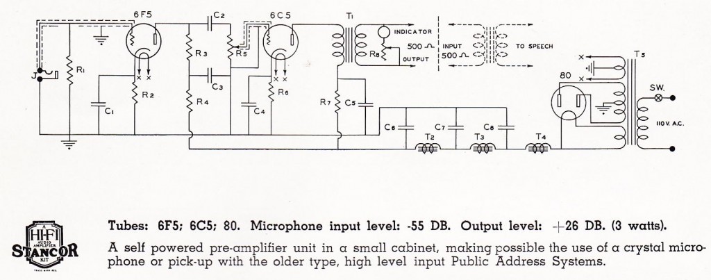
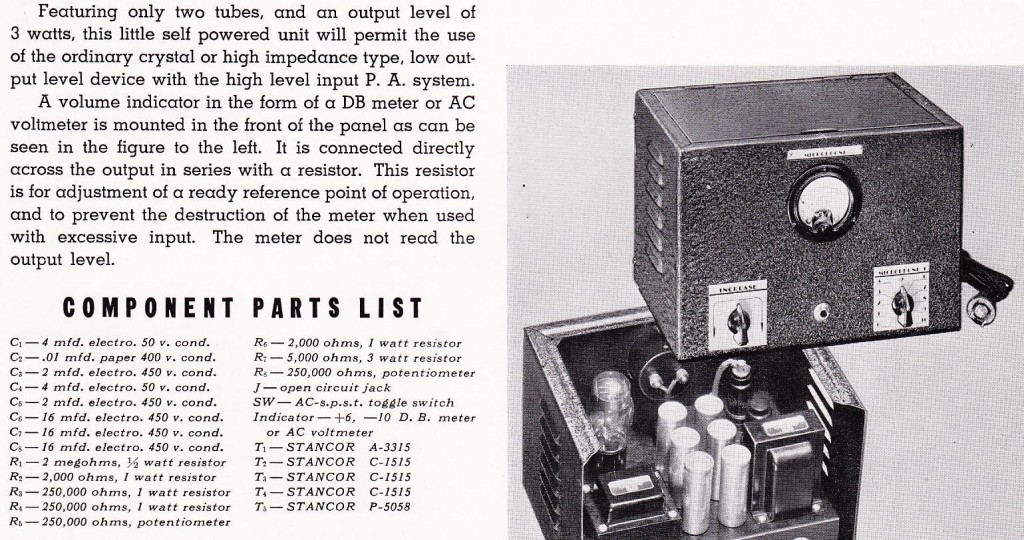 Above, the schematic and parts list for the ‘303,’ a microphone pre-amp. I will be building one of these shortly. I was most excited by this publication due to the 76 tubes in a few of the circuits. I am close to completion on a novel microphone preamp design that uses a 76 tube as the input stage and I am in-general trying to get more into the early ‘two-digit-designation’ tubes: the 75, the 76, the 42, 80, etc… we are looking back etc etc.
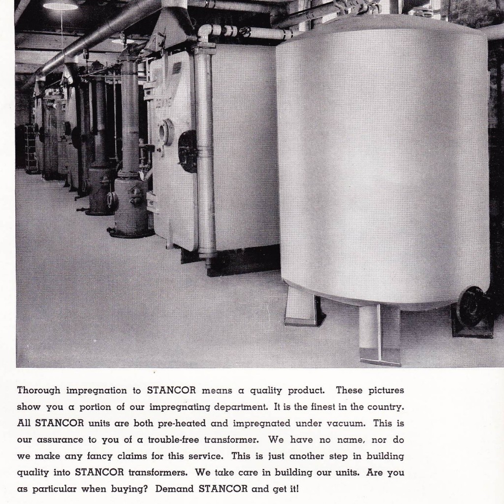 Above, an image of the Stancor factory which describes a certain transformer-manufacturing process which I will not put into text because I get enough porn spam as it is.
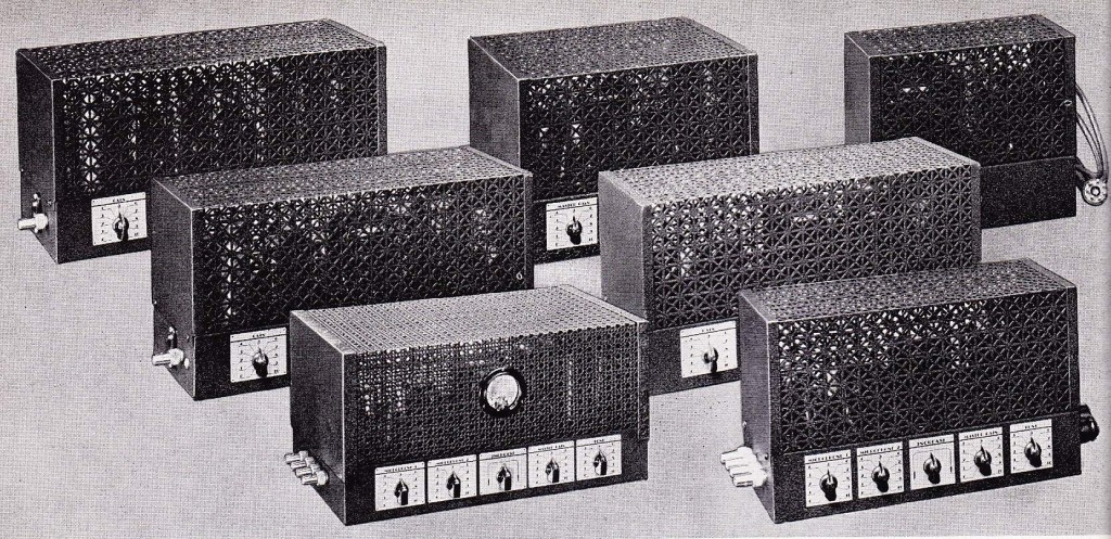 Several completed Stancor amplifier units
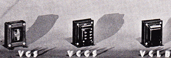 Above, several transformer units photographed for the catalog with their model-numbers included via practical photography. What a great design move this is. I bet we see a return to this product-photography technique in the coming years. ‘If you can find a way to do-it practically (rather than digitally), then do it practically!’

